
User's Manual

OPERATION
Thermistor Current Source
05_07 LDT-5100 7
CHAPTER 2
Thermistor Current Source
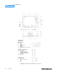
For a greater range of temperature sensing, two current sources are provided on
the LDT-5100; 100 µA and 10 µA. Each source is selectable on the
“THERMISTOR CURRENT” jumper (J5). The default setting from the factory is
100µA.
Note: If the jumper is removed, the 100 µA current source (default) is selected. The choice
of current source will depend on the thermistor sensor used. Please refer to LX Lightwave
Application Note #2, Selecting and Using Thermistors for Temperature Control.
Current Limit (J4)
The current limit selector (J4) allows the user to set the upper limit of the TE drive
current. The TE current limit is jumper selectable to five (5) values, 250mA,
500mA, 1A, 1.5A and 2A. The default limit is set to the minimum limit current of
250mA. The limit is for both positive and negative load currents. The limit current
value is selected by placement of a jumper at the indicated position on the
“CURRENT LIMIT” connector (J4). A jumper must be used in one of the five
positions in order for the LDT-5100 to function.
TEC Gain
The proportional term of the LDT-5100 control loop can be adjusted with the “TEC
GAIN” trim pot (R44). When adjusted fully clockwise, the TEC GAIN is in the MAX
position. This corresponds to a proportional term gain of 50. With the TEC GAIN
adjusted fully counter-clockwise, the proportional term gain will be 1.
Measurement/Control (J2)
Output Off
An output off control line is provided at pin 1 of the measurement / control
connector (J2). When no connection is made, this line is internally pulled high and
the output is turned on (current is provided to the TE output). This is also the
condition at power-up. If the control line is grounded, the output will be off (no
current provided to the TE output). The control line input is a MOSFET allowing a
large variation in “low” voltage levels.