
User's Manual

LDT-5100 5
CHAPTER 2
OPERATION
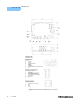
See Figure 2.1 for location and identification of control connectors and jumpers.
Thermistor Resistance Set Point
Two methods of thermistor R set point control are provided in the LDT-5100;
internal resistor or external resistor. A jumper, “RESISTOR SEL”, (J6) is used to
select which resistor is used as the set point reference for the control loop. (A
jumper on the left and center pins selects external resistor. Right and center pins
select internal resistor).
Note: A jumper must be present in one of the positions for the control loop to function.
Internal
In this mode, a 50 kΩ on board trim pot, “R SET” (R52) is used to set the control
resistance. Adjustment of this pot will cause the control loop to adjust the load
temperature so that the sensor thermistor value equals the trim pot resistance.
Although this will work in either thermistor current setting, improved accuracy will
result if the 100 µA range is used.
External
In this mode, the loop will use the resistance between pins 5 and 6 of the “TEC
I/O” connector (J1) as the set point. A fixed resistor should be used to achieve the
best load temperature stability. A variable resistor can also be used if fine
adjustment is required. The resistor value used will depend on the thermistor
sensor chosen and the current source range selected.