
User's Manual

INTRODUCTION
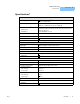
Specifications
1
4 LDT-5100
CHAPTER 1
1. All values tested after a one hour warm up period.
2. Additional current is needed if external LED indicators are used (approximately 10 mA per LED)
3. Higher voltage allowed with use of additional heat-sinking of mounting plate.
4. Use of an external precision resistor is the recommended method to set desired thermistor R.
5. Over any 24 hour period, controlling an LDM-4412 mount at 25
o
C with a 10 kΩ thermistor on 100 µA setting.
6. Open collector outputs for TEC open error, sensor open error and output on indicator can be used to control other functions such
as laser output disable line on the LDX-3100 current source.
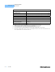
LED Indicators
Output On
PCB pads for external LED (10 mA) and open collector output
6
TEC Open Error
PCB pads for external LED (10 mA) and open collector output
6
Sensor Open Error
PCB pads for external LED (10 mA) and open collector output
6
GENERAL LDT-5100
Size 1.75” x 3.75” x 5.5” (44mm x 95mm x 139mm)
Weight 8.75 oz
Operating Temperature 0 to 50
o
C
Storage Temperature -40 to 70
o
C