User’s Guide Laser Diode Mount LDM-4990 ILX Lightwave Corporation · P. O. Box 6310 · Bozeman, MT, U.S.A. 59771 · U.S. & Canada: 1-800-459-9459 · International Inquiries: 406-556-2481 · Fax 406-586-9405 ilx.custhelp.com · www.ilxlightwave.
TA B L E O F C O N T E N T S TABLE OF CONTENTS Safety Information and the Manual . . . . . . . . . . . . . . . . . . . . . . . . . . . . . . . . . iii General Safety Considerations . . . . . . . . . . . . . . . . . . . . . . . . . . . . . . . . . . . . iii Safety Marking Symbols . . . . . . . . . . . . . . . . . . . . . . . . . . . . . . . . . . . . . . . . . iv Comments, Suggestions, and Problems . . . . . . . . . . . . . . . . . . . . . . . . . . . .
TA B L E O F C O N T E N T S ii LDM-4990
LIST OF FIGURES LIST OF FIGURES Figure 1.1 Exploded View of LDM-4990 . . . . . . . . . . . . . . . . . . . . . . . . . . . . 2 Figure 2.1 LDM-4990 Laser Mount Connections . . . . . . . . . . . . . . . . . . . . . 6 Figure 2.2 Laser Current Connector . . . . . . . . . . . . . . . . . . . . . . . . . . . . . . . 6 Figure 2.3 LDM-4409 TEC Connector . . . . . . . . . . . . . . . . . . . . . . . . . . . . . 7 Figure 2.4 Configuration Switch Labels . . . . . . . . . . . . . . . . . . . . . . . . . . . .
LIST OF FIGURES iv LDM-4990
SAFETY AND WARRANTY INFORMATION The Safety and Warranty Information section provides details about cautionary symbols used in the manual, safety markings used on the instrument, and information about the Warranty including Customer Service contact information.
SAFETY SYMBOLS SAFETY SYMBOLS This section describes the safety symbols and classifications. Technical specifications including electrical ratings and weight are included within the manual. See the Table of Contents to locate the specifications and other product information. The following classifications are standard across all ILX Lightwave products: • Indoor use only • Ordinary Protection: This product is NOT protected against the harmful ingress of moisture.
WA R R A N T Y WARRANTY ILX LIGHTWAVE CORPORATION warrants this instrument to be free from defects in material and workmanship for a period of one year from date of shipment. During the warranty period, ILX will repair or replace the unit, at our option, without charge. Limitations This warranty does not apply to fuses, lamps, defects caused by abuse, modifications, or to use of the product for which it was not intended.
WA R R A N T Y Comments, Suggestions, and Problems To ensure that you get the most out of your ILX Lightwave product, we ask that you direct any product operation or service related questions or comments to ILX Lightwave Customer Support. You may contact us in whatever way is most convenient: Phone . . . . . . . . . . . . . . . . . . . . . . . . . . . (800) 459-9459 or (406) 586-1244 Fax . . . . . . . . . . . . . . . . . . . . . . . . . . . . . . . . . . . . . . . . . . . . .
CHAPTER 1 INTRODUCTION AND SPECIFICATIONS This manual describes the LDM-4990 TO-Can Mount Laser Diode Mount and related accessories and options and explains their operation. This chapter provides an overview of the LDM-4990 and contains general information and specifications important in its use. You should read the entire manual to familiarize yourself with the operation of your LDM-4990 Laser Diode Mount before installing laser diodes.
CHAPTER 1 INTRODUCTION AND SPECIFICATIONS Product Overview removal and hose connectors for cooling water and nitrogen purge. TO-Can lasers are simply inserted into the socket under the access door on the top of the mount. Once seated, and with the correct device selector in position, closing the door locates and forces the diode against the hotplate.
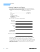
Specifications Laser Packages 9mm, 5.6mm, 5.4mm Laser Lead Length 6.4mm to 19mm Laser Pin-out1 Common cathode or common anode, three and four pin devices Input Connectors Laser Diode Current ILX standard female 9-pin D-sub Case Temperature Control ILX standard male 9-pin D-sub Ground Female banana jack Case Temperature Control Temperature Control Range2,3 -20oC to 85oC Maximum Thermal Load 500 mW Sensor Type 6A @ 4.5V Accuracy +0.5oC General Size (H x W x D) 4.74” x 4” x 1.5” (120.
CHAPTER 4 LDM-4990 1 INTRODUCTION AND SPECIFICATIONS Specifications
CHAPTER 2 OPERATION This chapter describes the electrical connection to and operation of the LDM-4990 TO-Can Laser Diode Mounting Fixture. Configuration options for the LDM-4990 and various laser package mounting is also discussed. The LDM-4990 is shipped from the factory with no configuration set for the laser pin-out. Operation of your laser will be impossible without first configuring the LDM-4990. Before installing your laser, please read the sections in this chapter for details on how to do this.
CHAPTER 2 OPERATION LDM-4990 Mount Electrical Connections Figure 2.1 LDM-4990 Laser Mount Connections The female 9-pin connector (P1) for the laser current is compatible with all ILX Lightwave current sources and cables. There are connections provided for laser cathode and anode, photodiode cathode and anode, and ground. The pinout diagram for this connector is shown in Figure 2.2. Figure 2.
Proper shielding of the current source and temperature controller signals is necessary to ensure proper noise-free performance. This is accomplished by grounding the shield on the interconnect cables to the controller and not to the mount. The CC-505 Temperature Control Cable provides this shielding automatically by connecting the 15 pin housing into the temperature controller. The CC-305S Current Source Cable, being symmetrical, must be oriented correctly to ensure proper grounding of the shield.
CHAPTER 2 OPERATION Configuring the LDM-4990 Configuring the LDM-4990 The LDM-4990, as shipped from the factory, is not configured for any laser. Therefore, the mount must be configured for your particular laser before operation. There is no real standard for pin numbering of these devices; most three pin devices are similar if not identical, however, some four-pin devices are numbered opposite.
OPERATION Configuring the LDM-4990 CHAPTER 2 For example, Figure 2.5 shows a TO-can laser with its associated pin assignments and configuration. The pins are assigned as shown in Table 2.1. Figure 2.5 Laser Diode Pin Assignment Table 2.1 Sample Pin Assignments Type A Type B Pin 1 Case LD Anode/Case Pin 2 LD Cathode LD Cathode Pin 3 PD Anode PD Anode Pin 4 LD Anode/PD Cathode PD Cathode For each type, the LDM-4990 configuration switches would be set as follows: Table 2.
CHAPTER 2 OPERATION Laser Diode Mounting Laser Diode Mounting Laser diodes are extremely susceptible to damage caused by electrostatic discharge and surge currents. To avoid early failure or damage to the device, workers and workbenches must be grounded at all times when handling or working with laser diodes. The LDM-4990 is designed to allow quick, easy insertion and removal of laser diodes in a 5.4 mm, 5.6 mm and 9.0 mm TO-can style package.
OPERATION Laser Diode Mounting CHAPTER 2 To install a laser diode, refer to Figure 2.7, and follow these steps: 1 Ensure that the mount has been configured for the correct pin-outs for the laser you are about to install. If it has not been configured, refer to instructions earlier in this chapter for more information. 2 Disable the output of any current controller connected to the mount. 3 Open the access door.
CHAPTER OPERATION Current Sources and Current Measurements 2 Current Sources and Current Measurements Do not exceed the specified current settings of the laser. Excessive drive current may cause laser failure. Operate the LDM-4990 Laser Diode Mount using any ILX Lightwave current source or temperature controller. Operation with other current sources or temperature controllers is also possible, provided that the correct wiring is observed (refer to Figures 2.4 and 2.5).
OPERATION Temperature Control CHAPTER 2 (Peltier) devices provide a simple, reliable solution to precise temperature control in many applications of optoelectronic devices. These solid-state devices can heat or cool small thermal loads to more than 60°C from ambient and achieve temperature stabilities of better than 0.001°C.
CHAPTER OPERATION Temperature Control 2 mount. Use a ½" open-end wrench to tighten the fittings. Use caution when tightening the fittings to avoid damaging the threads in the 4990 fixture. 3 Connect 1/4" I.D. flexible tubing to each fitting and to a water source and drain. Figure 2.8 LDM-4990 Water Connections Nitrogen Purge As the temperature within the LDM-4990 is driven to near ambient and below, the problem of condensation around the laser device and mount becomes a concern.
OPERATION Temperature Control CHAPTER 2 Figure 2.
CHAPTER OPERATION Installing OMH-6700 Series Measurement Heads 2 Installing OMH-6700 Series Measurement Heads The EMS-499 Measurement Head Option allows you to attach some OMH-6700 Series Measurement heads to the LDM-4990 for power and wavelength measurement of the device under test. To install an OMH-6700 Measurement Head, refer to Figure 2.10, and follow these steps: 1 Align the flat on the 6700 measurement head with the flat on the mounting post of the 4990 with the aperture facing down.
CHAPTER 3 MAINTENANCE No maintenance procedures are required for the LDM-4990 other than an occasional cleaning, as needed, to remove any accumulated dust or dirt from the hot plate. If the mount is not in use with a laser inserted, the access door should be closed. Insert plastic anti-static covers over the 9-pin laser current and temperature control connectors.
CHAPTER 18 LDM-4990 3 MAINTENANCE
CHAPTER 4 SAFETY Laser diodes used with the LDM-4990 Laser Diode Mount may emit infrared radiation which is invisible to the human eye. Extreme care must be taken to prevent the beam from being viewed either directly or through external optics or mirrors. Remove rings, jewelry, and other reflective materials when working with lasers. WARNING Viewing of emissions from the laser may cause eye damage. Use of protective goggles is recommended when operating these lasers.
CHAPTER 20 LDM-4990 4 SAFETY