
User's Manual

OPERATION
Back Panel Controls and Connections
06_07 LDT-5525 13
CHAPTER 2
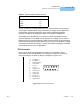
Table 2.1 SENSOR SELECT Switch Positions
The 10 µA and 100 µA designations are for the current source level; thermistor
sensor type is implied. When using a thermistor, the supply current depends on
the thermistor operating temperature range and the required temperature
resolution. Guidelines for setting this switch are contained in Appendix B.
The AD590 sensor operates as a current source which is proportional to the
sensed temperature. The LM335 sensor operates as a voltage source which is
proportional to the sensed temperature. Both of these sensors are approximately
linear over their operating ranges. When they are used, the constants C1 and C2
are used for a two-point conversion. For more information on setting the constants
for use with these sensors, see Appendix C.
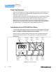
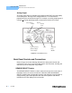
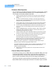
TEC Connector
At the right of center, when facing the back panel, you will find the 15-pin
D-connector for the TEC MODULE. This connector is used for the input and
output connections, as shown by the pin-out diagram of Figure 2.12.
Figure 2.3 Back Panel TEC Connector
SWITCH POSITION CODE
100 µA -01-
10 µA -02-
LM335 -03-
AD590 -04-
1
234
5
6
7
8
9
10
11
121314
15
1, 2 TE Module (+)
3, 4 TE Module (-)
5 TE Module Shield
6 Sensor Shield
7 Sensor (+)
8 Sensor (-)
9 Analog Ground
10 Control Signal
11 Voltage Limit
12 Current Limit
13 Temp. Limit
14 Booster Present
15 Digital Ground