
User's Manual

OPERATION
Back Panel Controls and Connections
12 LDT-5525
CHAPTER 2
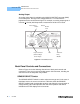
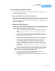
Analog Output
An analog output signal is available at the ANALOG OUTPUT connector (BNC)
on the front panel. This signal is a voltage between 0 - 5.0 volts which is
proportional to the measurement signal. For example, an analog output signal of
2.5 volts (
+0.5 volts) would represent a measurement of 50% of full scale.
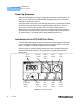
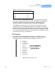
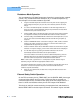
Figure 2.2 LDT-5525 Back Panel
Back Panel Controls and Connections
Refer to Figure 2.2 for the following discussions of back panel controls and
connectors. There are no user serviceable parts in the instrument, including the
external fuses in the AC power entry module.
SENSOR SELECT Switch
The SENSOR SELECT switch is used to select sensor type and, in the case of
thermistor sensor, the source current level. Table 2.4 shows the SENSOR
SELECT positions and corresponding position code. When the sensor switch is
changed during TEC mode operation, the new sensor position code will be
indicated on the TEC display for three seconds.
Sensor Select Chassis
Switch Ground
Post
15-pin Connector Fan AC Power
(Current Output Entry
Sensor Input) Module