Console Server User Manual 21 June 2001
Lightwave Communications, Inc. 100 Washington Street Milford, CT 06460 USA (800) 871-9838 • (203) 878-9838 • Fax: (203) 874-0157 Email: info@lightwavecom.com • Internet: www.lightwavecom.com LCI Asia/Pacific Postal address: P.O. Box 19 GlenIris VIC 3146 Australia Delivery address: 16 Network Drive Port Melbourne VIC 3207 Australia +61 3 9646 1144 • Fax: +61 3 9645 3377 Email: sales@lightwavecom.com.au • Internet: www.lightwavecom.com.
1.0 Product Description ........................................................................................................................................... 1 1.1 Features ........................................................................................................................................................ 2 2.0 System Overview............................................................................................................................................... 3 2.
7.0 User Access and Interface............................................................................................................................... 43 7.1 Terminal Card.............................................................................................................................................. 43 7.2 Network Card............................................................................................................................................... 43 7.3 Modem Card............
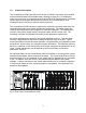
1.0 Product Description The ConsoleServer 3200 (also referred to as the CS 3200) is one of the most versatile network administration tools available today, allowing as many as 17 simultaneous users to access up to 32 connected devices via the RS-232C serial protocol. Pull-down menus help users navigate through all the functions of the ConsoleServer 3200, creating an easy-to-use way to access system resources.
1.
2.0 System Overview 2.1 Connect Up to Thirty-two RS-232C Compatible Ports The ConsoleServer 3200 is plug-compatible with any RS-232C device. These may be a variety of network servers, routers, or any other LAN/WAN computers on the network. Connections are made by routing the device signals through the switch cards to the appropriate user interface port. 2.2 64K FIFO Audit Trail The ConsoleServer 3200 stores the equivalent of approximately 100 screens worth of data per device port in a FIFO buffer.
The modem card connects directly to an ordinary phone jack (RJ11) to interface with a telephone network. The sys admin may designate a modem initialization string, or may use the default modem initialization string, which allows auto-answering on one ring.
3.0 System Components Each ConsoleServer 3200 consists of three major components: chassis, device cards, and access cards. 3.1 Chassis The chassis contains a front-panel LCD for quick system information that is available at all times. Two front panel buttons allow display selection and paging through displays (see section 10.0 for more information). The second component of the chassis is the power supply module.
address. The network card must be connected to a network that uses TCP/IP. Devices connected to the network card must be at 10 Mbits (no auto–negotiation) on 10-base T. 3.3.3 Modem Card The modem card allows dial-in access to the ConsoleServer 3200 and the servers attached to its device ports. The modem card supports baud rates up to 38.4 kbps, and will auto-detect the actual connection speed. Only one user at a time may access through the modem card, and only one modem card may be installed per unit.
4.0 Installation Instructions 4.1 Items in the Shipping Container a) ConsoleServer 3200 user manual b) User and Sys Admin Quick Reference Cards c) AC power cord d) Cable kit part number 200.0135 (four rubber feet included) e) ConsoleServer 3200 chassis with installed cards Additional adapters and cables may also be included in the shipping container if ordered. Large cable and adapter orders are usually shipped in separate containers. 4.
the unit. Alternate power cords are available for all national connector standards. The standard AC power module has dual inputs. The DC power module operates on –48 VDC, with 1.5 A maximum operating current, and 5 A maximum surge current. DC power must be externally protected against overcurrent. Each DC power module features dual power inputs. See Appendix D for further specifications and instructions regarding DC power requirements and installation. 4.
4. Firmly seat the adapter in the serial port. Screw down the adapter to secure it to the serial port. 5. Insert one end of the serial cable into the adapter until a click is heard. Insert the other end of the serial cable into port "A" of the control card, again until a click is heard.
5.0 Connecting Equipment to the ConsoleServer 3200 When connecting devices to the ConsoleServer 3200, be sure to use Lightwave Communications cables and adapters to ensure the proper transmission of data signals. If a device has an RJ45 serial port, use the manufacturer's cable included with the equipment to convert the RJ45 serial connector to a DB9 or DB25 connector, and then use a Lightwave Communications adapter to convert back to RJ45 to attach to the device port.
5.2 Network Card The network card runs at 10 Mbits, half-duplex, with no auto-negotiation. The device used to connect the ConsoleServer to the network (i.e., a hub or switch) must support this configuration. It is essential that the network device does not attempt autonegotiation; the ConsoleServer network card does not support this and will fail to establish a functioning link if auto-negotiation is used. Materials: • ConsoleServer 3200 network port • network point-of-connection (i.e.
5.4 Device Card The ConsoleServer 3200 is designed so that the default device port communications settings will match the communications settings of most Sun® server and workstation console ports (9600 baud, 8 data bits, no parity, one stop bit). Other equipment types (i.e., Cisco®) frequently use similar communications settings; check the manuals included with the equipment for the correct settings. The table below lists the default serial port communications settings for the ConsoleServer 3200.
Standard DB9 or DB25 installation: Materials: • ConsoleServer 3200 device port • device with RS-232-C serial console port • RJ45-terminated Cat 5 cable (standard LAN cable) • Lightwave adapter for serial console port 1. Attach the Lightwave adapter to the serial console port. 2. Connect the Cat 5 cable to the adapter. Connect the other end to the ConsoleServer 3200 device port. 3.
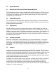
ConsoleServer 3200 Adapter Quick Checklist PORT CONFIG. SGI (Origin,O2, Octane, Onyx2) RJ45-RJ45 Cable Adapter DB9-RJ45 200.0070 Terminal Cable SGI Supplied Adapter DB25-RJ45 200.0066 Sun Terminal Cable Sun Supplied 14 Netra RJ45 DEC RS6000 Cisco Router/Hub Cisco w/RJ45 RJ45-RJ45 Cable DCE OR Adapter DB25-RJ45 200.0067 Included in cable kit 200.0135 RJ45-RJ45 Cable RJ45-RJ45 Cable RJ45-RJ45 Cable DCE OR Adapter DB25-RJ45 200.0067 200.
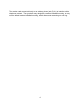
MODEM DEVICE DEVICE DEVICE DEVICE DEVICE DEVICE DEVICE CONTROL SWITCH DEVICE SWITCH A Fig. 3 General layout showing terminal port and device port numbers.
6.0 ConsoleServer 3200 Administration The following section outlines the administration functions and commands. The administration functions and commands are designed to enable the administrator to configure the ConsoleServer 3200 to fit the needs of the system application. User IDs, devices, terminals and access rights may be configured using the administration commands.
The serial terminal will display the following text at power-up: ConsoleServer3200 Boot V1.76 Copyright 2000 by Lightwave Communications, Inc. Identify Flash Flash ID OK Verifying Flash Image Starting system Lightwave Communications, Inc. ConsoleServer3200 Please wait...system initializing Checking non-volatile memory... 2048 Start checking and reading stored data Reading User Start up ......... All rights reserved.
6.1.2 Logging In, Network Connection UNIX_MACHINE# telnet 172.16.1.200 5000 Connecting to 172.16.1.200 port 5000... Escape sequence is ^] Welcome to the ConsoleServer3200 SysAdmin LCI3200>>login Please enter password: **** sys admin>> To log in on the ConsoleServer through a network connection, the network interface for the ConsoleServer first must be configured through the serial terminal (see section 6.5).
LOGGED OUT HELP SCREEN LCI3200>>help ConsoleServer 3200 Sys Admin [] - optional <> - parameter | - OR F1 - Display Help Screen (VT100 ABBREVIATIONS CONNECTIONS [/MONITOR] INFO LISTCARDS LISTDEVICES POWERSTATUS VERSION [/ALL|slot letter] - Command List must be specified mode) Show list of command abbreviations Show list of current connections (/monitor will auto-refresh) Report miscellaneous information Show list of installed cards Show list of device names Show status of power supplies Repor
1 will refer to the netterm subsystem and 2 will refer to the network subsystem on the card F1 - G1 switch cards (do not require updating) H1 - O1 device cards P1 - control card LINESPERPAGE [n] - Display/set number of lines before pause (n can be 0 to 99, 0 disables) LISTCARDS - Show list of installed cards LISTDEVICES - Show list of device names LISTUSERS [user id|/ALL] - Display list of users LOG [/ENABLE|DISABLE] - Enable/disable system events and set destination of event info LOGOUT,LOGOFF - Logout MOD
INFO LCIUPDATE LINESPERPAGE LISTDEVICES LISTUSERS LOGIN LOGOUT MODEM MODEMTIMEOUT NETWORK POWERSTATUS REBOOT RESTORE TELNETTIMEOUT TIMEOUT VERSION - (no abbreviation) - (no abbreviation) - LINESPP LINES LPP - LISTD LD - LISTU LU - LOGI - LO - (no abbreviation) - MODEMT MT - NET - PO PS - (no abbreviation) - (no abbreviation) - TELNETT TT - TIME - VER 6.1.5 Changing the Administration Password At the first login, the ConsoleServer 3200 will use the factory default password, PASS (all upper case).
6.2 Creating and Managing Users 6.2.1 Adding a User ID The ADDUSER command creates user IDs and assigns initial privileges. The following screen will be displayed when the command is used: sys admin>>ADDUSER Number of available user records: 200 Number of users defined: 0 Enter user id | USER ID > Press after typing the user ID. The user name is not case-sensitive. The next prompt asks for a password for the user ID. When the user logs in for the first time he will be asked for this password.
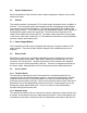
DEVICE DEVICE DEVICE DEVICE DEVICE DEVICE DEVICE DEVICE 1 5 9 13 17 21 25 29 A A A A A A A A 2 6 10 14 18 22 26 30 B B B B B B B B 3 7 11 15 19 23 27 31 C C C C C C C C 4 8 12 16 20 24 28 32 D D D D D D D D Fig. 4 Device Port Numbering HELPFUL HINT: Make a diagram or spreadsheet of connections indicating connections between devices and the ConsoleServer 3200 device ports as numbered above.
sys admin>>ADDUSER Number of available user records: 200 Number of users defined: 0 Enter user id | USER ID > tom Enter case sensitive password | PASSWORD > **** Re-enter case sensitive password | PASSWORD > **** 0-17 | MAX CONCURRENT LOGINS: 1> 2 Allowed devices example: 1-5,10 | DEVICES 0 > 1-4 Allowed listen devices example: 1-5,10 | DEVICES 0 > 0 Allow user to clear device buffer (Y/N) | YES > n Clear screen after a command (Y/N) | YES > n Enter user id | USER ID > Sys admin>> The above procedure has d
sys admin>>LISTUSERS 1: User id > PETE 2: User id > KEVIN 3: User id > TONY sys admin>>LISTUSERS /ALL 1: User id > PETE Allowed devices > 1-32 Allowed listen devices > 1-32 Max logins > 17 Allow user to clear device buffer > YES Clear screen after a command > YES 2: User id > KEVIN Allowed devices > 1-32 Allowed listen devices > 1-32 Max logins > 17 Allow user to clear device buffer > YES Clear screen after a command > YES 3: User id > TONY Allowed devices > 1-32 Allowed devices > 1-32 Max logins > 17 Allow
To delete a user ID using the record number, specify the number as a qualifier after the DELETEUSER command in the form DELETEUSER /N, where N is the user record number. 6.3 Devices Command Device port parameters must be defined by the sys admin using the DEVICES command. If a single device port is to be changed, the port number must follow the DEVICES command. If the DEVICES command is entered by itself, the configuration of all device ports will be listed.
sys admin>>terminal 1 Enter accepts present value T1: 0=9600, 1=19200, 2=38400, 3=57600 T1: 0=1, 1=2 T1: 0=None, 1=Odd, 2=Even T1: 0=8, 1=7, 2=6 T1: 0=DCE, 1=DTE T1: 0=XON/OFF, 2=RTS/CTS Card installed, settings updated | | | | | | BAUD RATE: 9600> STOP BITS: 1> PARITY: None> DATA BITS: 8> EQUIP PORT TYPE: DCE> FLOW CONTROL: XON/XOFF> sys admin>> Device port location reference and device name template: H I J K L M N O A list of device port names and their corresponding port number may be displa
sys admin>>TERMINALS 1 Enter accepts present value T1: 0=9600, 1=19200, 2=38400, 3=57600 T1: 0=1, 1=2 T1: 0=None, 1=Odd, 2=Even T1: 0=8, 1=7, 2=6 T1: 0=DCE, 1=DTE T1: 0=XON/OFF, 1=DTR/DSR, 2=RTS/CTS Card installed, settings updated | | | | | | BAUD RATE: 38400> STOP BITS: 1> PARITY: None> DATA BITS: 8> EQUIP PORT TYPE: DTE> FLOW CONTROL: XON/XOFF> sys admin>> Terminal port connection location reference template: B 6.
The NETWORK command will either display the network settings of the installed network cards or change those settings depending on which command qualifier is used. sys admin>>NETWORK N-B: IP address N-B: Subnet Mask N-B: Enter Default Gateway address N-B: Enter 2nd Dest. Network N-B: Enter 2nd Netmask N-B: Enter 2nd Gateway address N-B: BOOTP at startup? N-C: IP address N-C: Subnet Mask N-C: Enter Default Gateway address N-C: Enter 2nd Dest.
sys admin>>NETWORK /ALL Enter accepts present value N-B: Enter IP address | 000.000.000.000> N-B: Enter Subnet Mask | 255.255.255.255> N-B: Enter Default Gateway address | 255.255.255.255> N-B: Enter 2nd Dest. Network | 255.255.255.255> N-B: Enter 2nd Netmask | 255.255.255.255> N-B: Enter 2nd Gateway address | 255.255.255.255> N-B: BOOTP at startup? | Y> Save changes and update card? Yes or No: No> N-C: Enter IP address | 000.000.000.000> N-C: Enter Subnet Mask | 255.255.255.
sys admin>>NETWORK B Enter accepts present value N-B: Enter IP address | 000.000.000.000> 172.16.1.1 N-B: Enter Subnet Mask | 255.255.255.255> 255.255.255.0 N-B: Enter Default Gateway address | 255.255.255.255> 172.16.1.200 N-B: Enter 2nd Dest. Network | 255.255.255.255> N-B: Enter 2nd Netmask | 255.255.255.255> N-B: Enter 2nd Gateway address | 255.255.255.
sys admin>>MODEM Enter accepts present value Init string | > ATB2H0 Save changes and update modem card? Yes or No: No>yes Modem card not installed in slot A, init string saved Sys admin>MODEM /DEFAULT Current modem init string is: ATB2H0 Set modem to factory default value of: ATH0S0=1 (write out YES) Yes or No: No>yes Modem card not installed in slot A, init string saved sys admin>> The sys admin may also reset the initialization string to the default value by entering the command with the default qualifie
sys admin>>CONNECTIONS Terminal Connection List 01 KEVIN 01 SERVER 02 00 03 00 04 00 05 00 06 00 07 00 08 00 09 00 10 00 11 00 12 00 13 00 14 00 15 00 16 00 17 ( ( ( ( ( ( ( ( ( ( ( ( ( ( ( ( Monitor Channel Channel Channel Channel Channel Channel Channel Channel Channel Channel Channel Channel Channel Channel Channel mode ) present present present present present present present present present present present present present present present ) ) ) ) ) ) ) ) ) ) ) ) ) ) ) sys admin>> T
6.7.
6.7.4 INFO Command sys admin>>INFO A Slot A1: Modem: No Active Call Timeout = 1 mins. Current Modem State: in command mode Modem Init String: ATH0S0=1 Modem error: none sys admin>INFO C Slot C2: 0 Active Telnet Sessions Timeout = 1 mins. Ethernet Address: 00-30-31-00-00-4F IP=172.16.1.31 SM=255.255.255.0 GW=172.16.1.151 2nd route: IP=255.255.255.255 SM=255.255.255.255 GW=255.255.255.
• • The primary IP information, including: IP address, subnet mask, and gateway The secondary IP information, including: destination address, subnet mask, and gateway The terminal and device cards will return the following information: • • • • • • • • • • The terminal or device port number The port letter as indicated on card label Equipment port type (DCE or DTE) Baud rate Parity; N=none, E=even, O=odd Data bits Stop bits Flow control type Status of RTS line; 0=off, 1=on Status of DTR line; 0=off, 1=on
no time/date stamp on system activity. If a time/date stamp is required, it must be provided by the system capturing the data output. Connection instructions for the logging port: 1. Turn on power to the terminal or computer. If using a computer, start the desired communication program. The terminal or communications program used must be in VT100 emulation mode 2. Ensure that the communications settings are correct.
6.8.1 LINESPERPAGE Command sys admin>>LINESPERPAGE Lines per page set to 22 sys admin>LINESPERPAGE 10 Lines per page set to 10 sys admin>> The LINESPERPAGE command allows the sys admin to change the number of lines displayed per terminal page on the control card port before the MORE prompt is displayed. The number of lines to display per page is entered after the command. Entering the command without a number following will display the current amount of lines displayed per page.
The BREAK command allows the sys admin to disconnect a user from the device port to which they were connected if they are in monitor, listen, or direct mode. The user is still logged in after the connection is broken, but there is no longer any connection between the terminal port and the device port. The sys admin must specify the terminal port number (as listed with the CONNECTIONS command) of the connection to be severed when using the BREAK command.
The TELNETTIMEOUT command allows the sys admin to define the amount of time that a network card may have an idle telnet session before breaking the network connection. A telnet session is considered to be idle if no characters are sent from the user’s terminal. Once the time limit has been reached, the user will be logged out and the network connection will be broken. The connection will be broken if there is no activity at any login level (from logged out up to direct mode).
the ConsoleServer 3200 to restore the system settings. It is not possible to use the BACKUP and RESTORE commands from a network sys admin session. Before beginning either the backup or restore processes, make sure that there are no users logged in to the ConsoleServer 3200 by using the CONNECTIONS command. If there are any users logged in, notify them to log out immediately or forcibly log them out using the FORCELOGOUT command.
To change the system prompt to the default (LCI3200>), use the command PROMPT /DEFAULT. 6.12 Updating the ConsoleServer 3200 Software As new features are added to the ConsoleServer 3200, new versions of the system software will become available. The sys admin may enter the ConsoleServer 3200 update mode using the command LCIUPDATE (which may never be abbreviated).
7.0 User Access and Interface 7.1 Terminal Card Each terminal card has four (4) RJ45 connector ports to which a terminal may be attached, giving a maximum of 16 physically connected terminals per ConsoleServer 3200 unit. The terminal card may be installed in slots B, C, D, or E.
At power-up, the network card does not respond to network connect requests until the control card has completed its system initialization. Once the power-up sequence is complete, the network card obtains its network parameters from the control card, and is ready to accept connections over the network. It is important to note that the network card does not retain its network parameters (i.e., IP address, subnet mask, gateway address) if moved from one card slot to another.
sections above). This indicates that the user is not currently logged in and that no servers may be reached through the ConsoleServer 3200. The prompt will change to reflect the level in which the user is, and in monitor mode, will also indicate which server is selected. The help screens also change according to the user's login level. There are separate help screens for a logged out user, a logged in user, and a user in monitor (a.k.a. device) mode.
MONITOR (A.K.A.
7.5 Logging In and Changing Passwords F2 PULL-DOWN MENU SHOWING INITIAL MENU CHOICES ┌─────────────────┐ │ LOGGED OUT MENU │ ├─────────────────┤ │ USER LOG IN │ │ SYSTEM INFO │ │ DISPLAY HELP │ └─────────────────┘ To login, the user must type LOGIN at the LOGGED OUT> prompt or select USER LOG IN from the pull-down menu. The user ID may also be entered as a command qualifier after the login command.
password and press . The ConsoleServer 3200 will then prompt the user for the new password by displaying the prompt PLEASE ENTER NEW PASSWORD. The user should enter the new password (which may be up to ten alphanumeric characters and is case-sensitive) at this prompt and press . After entering the new password, the user will be asked to verify the new password by the prompt PLEASE VERIFY PASSWORD.
are logged in, which devices they have currently selected, and which mode they are in. Users may also view this information by selecting DISPLAY CONNECTED LIST from the pull-down menu when logged in. 7.
not have permission to access a server, the ConsoleServer 3200 will display the message NO ACCESS TO DEVICE CHANNEL, and the connection will not be made. The user may exit from their current device port first by using the EXIT command or selecting EXIT FROM SERVER from the pull-down menu to free the device port for use by other users. A user may not select a server that is already selected by another user.
F2 PULL-DOWN MENU TO LISTEN TO A DEVICE PORT PART 2 ┌───────────────────────────────────────────────────┐ │ SELECT SERVER │ ├───────────────────────────────────────────────────┤ │01 – DEVICE_1 02 - DEVICE_2 │ │03 - DEVICE_3 04 - DEVICE_4 │ │05 06 │ │07 08 │ │09 10 │ │11 12 │ │13 14 │ │15 16 │ │17 18 │ │19 20 │ │21 22 │ │23 24 │ │25 26 │ │27 28 │ │29 30 │ │31 32 │ └───────────────────────────────────────────────────┘ To monitor another user's server session, the user must type LISTEN followed by the device
7.10 Direct Mode F2 PULL-DOWN MENU SHOWING DEVICE (A.K.A.
software used. It is also recommended that the user avoid combinations of the key and other keys, as these combinations are usually reserved for sending and receiving special characters through the terminal. When the user changes the escape sequence, a window with the hexadecimal representation of the old escape sequence will appear. Pressing to exit from the edit prompt will not work; it will add additional characters (hexadecimal value 1B) to the direct mode escape sequence.
When at the monitor mode prompt, the user may view the contents of the buffer using the commands TOP, BOTTOM, NEXT, PREVIOUS, FORWARD, and REVERSE, or by selecting the commands DISPLAY NEXT PAGE, DISPLAY PREVIOUS PAGE, GOTO BEGINNING OF BUFFER, GOTO END OF BUFFER, FORWARD N LINES, and REVERSE N LINES from the pull down menu. The monitor mode prompt will appear at the bottom of the displayed buffer data, and the user may enter commands normally at this prompt.
FORWARD FORWARD N LINES REVERSE REVERSE N LINES skip forward N lines in buffer skip back N lines in buffer The commands FORWARD and REVERSE must be followed by the number of lines the user wants to move in the buffer. The command will not execute if the number of lines is omitted. The user may also clear the buffer by using the command CLEAR or by selecting CLEAR BUFFER from the pull-down menu. All data stored in the device buffer will be erased and is not recoverable.
8.0 The Break Generation Sequence F2 PULL-DOWN MENU TO CHANGE BREAK SEQUENCE ┌──────────────────────────┐ │ LOGGED IN MENU │ ├──────────────────────────┤ │ CONNECT TO SERVER │ │ DIR CONNECT TO SERVER │ │ LISTEN TO SERVER │ │ DISPLAY CONNECTED LIST │ │ DISPLAY SERVER NAMES │ │ DISPLAY ACTIVE DEVICES │ │ LOGOUT │ │ CHANGE PASSWORD │ │ CHANGE DIRECT MODE ESC │ │ CHANGE BREAK MODE ESC │ │ DISPLAY HELP │ └──────────────────────────┘ The user may find it necessary to send a break to the selected server.
9.0 Displaying System Information F2 PULL-DOWN MENU TO DISPLAY SYSTEM INFO ┌─────────────────┐ │ LOGGED OUT MENU │ ├─────────────────┤ │ USER LOG IN │ │ SYSTEM INFO │ │ DISPLAY HELP │ └─────────────────┘ The user access cards are capable of displaying information about their software and communications settings. This information can be accessed only at the LCI3200> prompt by selecting SYSTEM INFO from the pull-down menu, or typing the command INFO or MISC at the prompt.
10.0 Front Panel Display Information: The up/down arrow keys are used to scroll through multi-page displays. Lightwave Communications, Inc. The LCD displays the panel below at power up time. This will be displayed for as long as five minutes while the ConsoleServer 3200 is in the initialize mode. After the ConsoleServer 3200 has gone through the initialization phase, the terminal connection list will automatically be displayed.
Panel 3 (press down) Panel 4 (press down) The next series of panel shows the port number along with the name of the device connected to that port.
Panel 7 (press down) Panel 8 (press down) Panel 9 (press down) The next series of panels displays the inventory of cards that are installed in the chassis.
Panel 12 (press down) The last panel displays the status of the power supplies.
Appendix A – Adapter & Connector Pinouts RJ45 ConsoleServer 3200 Terminal / Device (DTE) RJ45 ConsoleServer 3200 Terminal / Device (DCE) Tx 3 Tx 3 Rx 2 Rx 2 RTS 7 RTS 7 CTS 8 CTS 8 DTR 4 DTR 4 DSR 6 DSR 6 DCD 1 DCD 1 SG 5 SG 5 pin 1 100 Washington Street, Milford CT 06460 800 871-9838 * Fax 203 874-0157 * www.lightwavecom.
pin 1 DB25 MALE RJ45 2 3 3 2 4 7 5 8 6 6 7 5 8 1 20 4 100 Washington Street, Milford CT 06460 800 871-9838 * Fax 203 874-0157 * www.lightwavecom.com Title: RJ45 Receptical to DB25M Adapter Part Number 200.0066 Drawing Number Size: File: 63 A 700.200.0066 ConsoleServer 3200 Sheet 200d0066.
pin 1 DB25 FEMALE RJ45 2 3 3 2 4 7 5 8 6 6 7 5 8 1 20 4 100 Washington Street, Milford CT 06460 800 871-9838 * Fax 203 874-0157 * www.lightwavecom.com Title: RJ45 Receptical to DB25F Adapter Part Number 200.0067 Drawing Number Size: File: 64 A System: 700.200.0067 ConsoleServer 3200 200d0067.
pin 1 DB9 FEMALE RJ45 1 1 2 2 3 3 4 4 5 5 6 6 7 7 8 8 100 Washington Street, Milford CT 06460 800 871-9838 * Fax 203 874-0157 * www.lightwavecom.com Title: RJ45 Receptical to DB9F Adapter Part Number Drawing Number Size: File: 65 200.0070 700.200.0070 System: ConsoleServer 3200 A Sheet 200d0070.
66
Appendix B – Field Update of Console Server 3200 Flash Memory B.1 Introduction The system administrator may desire to update the software held in flash memory. The modem, terminal, network, device, and control cards all have field-programmable flash memory. Switch cards are not programmable in the field. The flash software may be updated by two means: through a direct serial connection, or via network. B.
application code version, which is listed first) is greater than 1.70, then Kermit may be used to transfer the binary update files; otherwise, Xmodem must be used. B.3 Getting Started Before initiating the flash update process, the system administrator must check that there are no active users on the ConsoleServer 3200 by using the CONNECTIONS command. If there are any users logged in, they should be notified to log out immediately or forcibly logged out by using the FORCELOGOUT command. B.3.
to be updated at this prompt. See page XX for slot letter ID’s. For most cards, the processor number will be 1; network cards have two processors: processor 1 is the user interface to the network card (use netterm.bin), while processor 2 is the network interface (use network.bin). After the system administrator enters the card ID, the ConsoleServer 3200 will return the prompt YY IS CONSOLESERVER3200 CCCCCC BOOT VX.XX (DDD DD DDDD) START XMODEM TRANSFER OF UPDATE....
The tftp server must be specified by a numerical IP address. The file path and name on the server is specified after the IP address. local serial connection: sys admin>> tftp /b 172.16.1.1:fdevice.bin Starting tftp download................................................. ....................................................................... ......................... Download complete. sys admin>> In the example above, the sys admin is connected through a local serial connection.
B.6 Ending the Flash Update Slot (letter) Processor (number) Ex. C1 Starting system (exit to restart system): EXIT ConsoleServer 3200 Control Boot V1.26 (Jun 15 1999) Copyright 1999 by Lightwave Communications, Inc. All rights reserved. Starting system Lightwave Communications, Inc. ConsoleServer 3200 Please wait...system initializing Checking page 30 Once the flash update is completed for all selected cards, the system administrator must type EXIT at the update prompt.
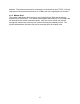
72 Slots for programming purposes MODEM TERMINAL TERMINAL TERMINAL TERMINAL SWITCH SWITCH DEVICE DEVICE DEVICE DEVICE DEVICE DEVICE DEVICE DEVICE CONTROL I 0 A A A A A A A A A A A A B B B B B B B B B B B B C C C C C C C C C C C C D D D D D D D D D D D D A I 0 B
Appendix C – System Specifications C.1 Physical Width: Depth: Height: 17.25 inches (43.82 cm) 14.75 inches (37.47 cm) 5.25 inches (13.34 cm) Rack size: 3u high, mounts in EIA-standard 19-inch rack Weight fully loaded: 20 lbs. (9.08 kg) C.
C.4 Interface C.4.1 Terminal and Device Connector: Specification: Maximum baud rate: Minimum baud rate: RJ45 with adapters for EIA-standard connectors (DB9 and DB25) EIA-232 38400 9600 C.4.2 Network Connector: Protocol: Maximum speed: Auto-negotiation: RJ45 TCP/IP (version 4) 10 Mbits, half duplex NOT SUPPORTED C.4.3 Modem Format: Maximum speed: C.
Appendix D -DC Power The DC power version of the ConsoleServer 800 must be installed in a restricted access location. Per the intent of the National Electrical Code, a restricted access location is an area intended for access by qualified or trained personnel only, with access controlled by some sort of locking mechanism, such as a key lock or access card system.
Input voltage: Minimum voltage: Maximum voltage: Maximum operating current: Maximum input surge current: -48 VDC -40 VDC -60 VDC 1.
The DC power source must be: • electrically isolated from any AC source • reliably connected to earth • capable of providing up to 100 Watts of continuous power D.2 Overcurrent Protection Overcurrent protection requirements: • 10 Amp trip • double pole • fast trip • DC rated • • D.3 Overcurrent protection devices (e.g., circuit breakers) must be provided as part of each equipment rack, and are not included with the ConsoleServer.
Appendix E – Command Abbreviations Most, but not all, commands available on the ConsoleServer 3200 may be abbreviated. The following list outlines the allowed maximum abbreviations for all commands. Command qualifiers for a command may be found immediately below that command.
Terminal, Network, and Modem Commands: command bottom bye changepswd clear connections devlist direct diselect editbrk editesc exit forward listen login logout, logoff next passwd previous reverse select top abbreviation bo bye ch cl co de dir dis editb edite ex f li logi logou, logof n pa pr r se t 79
Appendix F – Hexadecimal ASCII Code Equivalent characters in italics are non-printing characters or signals.
Hexadecimal Code 40 41 42 43 44 45 46 47 48 49 4A 4B 4C 4D 4E 4F 50 51 52 53 54 55 56 57 58 59 5A 5B 5C 5D 5E 5F Equivalent Character @ A B C D E F G H I J K L M N O P Q R S T U V W X Y Z [ \ ] ^ _ Hexadecimal Code 60 61 62 63 64 65 66 67 68 69 6A 6B 6C 6D 6E 6F 70 71 72 73 74 75 76 77 78 79 7A 7B 7C 7D 7E 7F 81 Equivalent Character ` a b c d e f g h i j k l m n o p q r s t u v w x y z { | } ~ DEL
Index Abbreviations – 16, 19-20, 45, 76-77 Backing up system settings – 39-40 Breaks – 2, 5 editing generation sequence - 55 sending - 55 Buffers – 2, 3, 25, 49 clearing content – 22, 54 viewing content – 49, 52-54 Cards – 1-6 listing installed cards – 33, 59-60 processors – 34, 67-68 slot letters – 33, 39, 67-68, 71 system information (INFO command) – 34-35 Connections to Devices – 3, 5-6 breaking (from sys admin) – 37-39 breaking (from user) - 49 checking (from front panel) – 57-58 checking (from sys admi
see also: User Network Card – 1-3, 5-6 checking settings – 34-35 connecting to – 42-43 idle timeout – 38-39 setting parameters – 27-30 see also: User Passwords – 1, 3 17-18, 46-47 changing sys admin - 20 changing user – 21, 23, 40-47 Power Supplies – 1, 5 checking status – 35, 60 Rack Mount - 7 Restoring System Settings - 40 Software - 1 updates – 41, 66-71 version – 33, 56, 70 Sys Admin – 14, 16-41 changing password - 20 connecting terminal – 8-9 logging in – 17-18 logging out - 18 timeout - 37 Terminal Ca
directly interacting with device port – 51-52 editing break sequence - 55 editing direct mode escape sequence – 51-52 logging in - 46 logging out - 47 selecting device – 48-49 84