
Manual


LW20 / SF20 LiDAR sensor
Product manual
5. How to communicate with the LW20 using the graphical interface
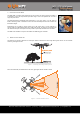
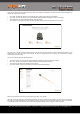
To use the graphical interface to setup and test the LW20 you will need to connect the serial port of the LW20 to the USB port on a
PC. This is done using a serial-to-usb converter such as the TTL-232R-3V3-WE converter cable from FTDI (http://www.ftdichip.com/
Products/Cables/USBTTLSerial.htm). This converter provides both the signals and power supply to the LW20.
Figure 4 :: Connection to a USB converter cable
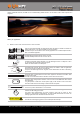
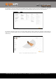
Once the converter is wired up to the LW20, prepare the Terminal application on the PC as follows:
•
Download and instal the latest Terminal application from the LightWare website
•
Open the Terminal application
•
Select the “Settings” icon
•
Set the baud rate to 115200
•
You can tick the “Remember settings” box if you intend to use this configuration again
•
Apply the change to close the dialog window
Figure 5 :: Setting the baud rate for LW20 communications
To establish communication between the LW20 and the graphical interface:
•
Plug the LW20 converter into a USB port on the PC
•
Click the “Connect” icon - a notice of the connection and its associated USB port number should become visible on the toolbar
•
Press the “LW20” icon - this opens the graphical interface home screen
LW20 / SF20 LiDAR - Product manual - Revision 9 | of | © LightWare Optoelectronics (Pty) Ltd, 2018 | www.lightware.co.za 8 28