
Manual


LW20 / SF20 LiDAR sensor
Product manual
Table of contents
Table of figures
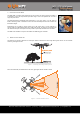
Figure 1 :: Measuring exact height above ground 3 ......................................................................................................
Figure 2 :: Collision avoidance zones 3 .....................................................................................................................
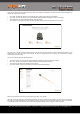
Figure 3 :: Autonomous vehicle navigation 4 ..............................................................................................................
Figure 4 :: Connection to a USB converter cable 6 ........................................................................................................
Figure 5 :: Setting the baud rate for LW20 communications 6 ..........................................................................................
Figure 6 :: The graphical interface Home screen 7 .......................................................................................................
Figure 7 :: The graphical interface Setup screen 7 .......................................................................................................
Figure 8 :: The graphical interface Parameters screen 8 ................................................................................................
Figure 9 :: The graphical interface Operate screen 8 ....................................................................................................
Figure 10 :: Connection to a USB converter cable 9 .....................................................................................................
Figure 11 :: Setting the baud rate for LW20 communications 9 ........................................................................................
Figure 12 :: Arrangement of screens in terminal emulation mode 10 .................................................................................
Figure 13 :: Connection to a Devantech USB-ISS module 11 .............................................................................................
Figure 14 :: The LightWare Terminal application top level window showing the toolbar 11 .......................................................
Figure 15 :: Selecting the Devantech I2C-ISS converter 11 ..............................................................................................
Figure 16 :: I2C test dialog box showing command buttons 12 .........................................................................................
Figure 17 :: Initial setup using the GUI or terminal emulation 14 ......................................................................................
Figure 18 :: Servo connections 15 ...........................................................................................................................
Figure 19 :: Setting up the electrical and mechanical characteristics of the servo 15 .............................................................
Figure 20 :: Setting the servo’s limits of motion using the PWM values 16 ...........................................................................
Figure 21 :: Setting the servo’s PWM scale 16 .............................................................................................................
Figure 22 :: Setting up the servo’s scanning characteristics 17 ........................................................................................
Figure 23 :: The effect of servo lag with no correction and after applying a 2.5 degree correction 17 .........................................
Figure 24 :: Reducing the field of view to avoid detecting the landing legs on a drone 18 .......................................................
Figure 25 :: Uni-directional scanning for higher precision 18 ...........................................................................................
Figure 26 :: Setting the alarms to warn of nearby objects 19 ..........................................................................................
Figure 27 :: Setting two dimensional alarms 19 ...........................................................................................................
Figure 28 :: Laser radiation information and labels 20 ..................................................................................................
Figure 29 :: Dimension drawings of the LW20 and SF20 20 ..............................................................................................
Figure 30 :: Heat sink contact area 22 .....................................................................................................................
Figure 31 :: Serial and power cable 23 .....................................................................................................................
Figure 32 :: Pinout diagram 23 ...............................................................................................................................
Product ordering codes
Product ordering codes 2 .....................................................................................................................................
1. Overview of the LW20 4 ...................................................................................................................................
2. What can the LW20 do? 4 .................................................................................................................................
3. What are the main characteristics of the LW20? 5 ...................................................................................................
4. Specifications of the LW20 / SF20 7 ....................................................................................................................
5. How to communicate with the LW20 using the graphical interface 8 .............................................................................
6. How to communicate with the LW20 using a terminal emulator 11 ...............................................................................
7. How to communicate with the LW20 using a controller 15 ..........................................................................................
8. How to do an initial setup of the LW20 16 .............................................................................................................
9. How to set up a scanning LiDAR using a digital servo 17 ............................................................................................
10. How to set up the alarms 21 .............................................................................................................................
11. Limitations 21 ..............................................................................................................................................
12. Instructions for safe use 22 ..............................................................................................................................
Appendix A :: Dimension drawings 22 .......................................................................................................................
Appendix B :: Cables and connections 23 ...................................................................................................................
Appendix C :: Complete command set for machine-to-machine communications 24 ................................................................
Revision history 28..............................................................................................................................................
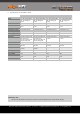
Model family
Model name
Model description
LW20
LW20/ B ( 50 m)
LiDAR sensor with serial and I2C output, max 50 m
LW20
LW20/ C ( 100 m )
LiDAR sensor with serial and I2C output, max 100 m
SF20
SF20/B (50 m)
Open frame LiDAR sensor with serial and I2C output, max 50 m
SF20
SF20/C (100 m)
Open frame LiDAR sensor with serial and I2C output, max 100 m
LW20 / SF20 LiDAR - Product manual - Revision 9 | of | © LightWare Optoelectronics (Pty) Ltd, 2018 | www.lightware.co.za 2 28