
Manual

LW20 / SF20 LiDAR sensor
Product manual
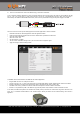
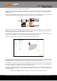
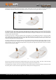
8. How to do an initial setup of the LW20
Using the GUI, Terminal or machine commands the measuring characteristics of the LW20 can be tailored to suit different
applications. The primary settings can be found by pressing the “Laser” button under the “Setup” tab of the GUI or on the main
menu screen of the terminal.
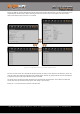
Figure 17 :: Initial setup using the GUI or terminal emulation
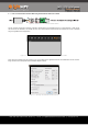
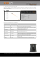
Details of the initial settings are given in the table below.
Setting name
Range of values
Description
Mode (update rate)
48 … 388 readings per second
Sets the rate at which distances are measured.
Zero distance offset
-10.00 … 10.00 meters
Moves the point at which the measured distance reads zero. This is to
correct for errors introduced by the mounting position.
Lost signal confirmation
1 … 250
Sets the number of readings that must be taken before a lost signal or
out-of-range condition is reported. This value prevents brief losses of
signal from affecting the distance results.
Alarm A distance
0 … 100 meters
Sets the activation distance of alarm A. This is the distance below which
the alarm changes state from ‘0’ to ‘1’.
Alarm B distance
0 … 100 meters
Sets the activation distance of alarm B. This is the distance below which
the alarm changes state from ‘0’ to ‘1’.
Alarm hysteresis
0 … 10 meters
The alarm hysteresis prevents the alarms from switching rapidly between
states when the target surface is at the activations distance. Activation
occurs at the set distance minus the hysteresis distance and deactivation
occurs at the set distance plus the hysteresis distance.
Serial port baud rate
9600 … 921600
Select the baud rate for the serial communication port. Note that new
values take effect after they are saved and power is cycled, the factory
default is 115200.
I2C address
0x00 … 0x7F
The address of the LW20 on the I2C bus, the factory default is 0x66.
LW20 / SF20 LiDAR - Product manual - Revision 9 | of | © LightWare Optoelectronics (Pty) Ltd, 2018 | www.lightware.co.za 16 28