LW20 / SF20 LiDAR sensor Product manual The compact LiDAR sensor for drones, autonomous vehicles and robots Table of contents Features: • Small size laser rangefinder when weight and size are critical • Long range measurements up to 100 meters to sense remote objects • Up to 388 readings per second for fast detection of obstacles • IP67 enclosure prevents damage from water and dust • Built-in drivers to make a scanning LiDAR by adding a digital servo • First and last return signals are available to suit
LW20 / SF20 LiDAR sensor Product manual Table of contents Product ordering codes ..................................................................................................................................... 2 1. Overview of the LW20 ...................................................................................................................................4 2. What can the LW20 do? .................................................................................................................
LW20 / SF20 LiDAR sensor Product manual Disclaimer Information found in this document is used entirely at the reader’s own risk and whilst every effort has been made to ensure its validity, neither LightWare Optoelectronics (Pty) Ltd nor its representatives make any warranties with respect the accuracy of the information contained herein. LW20 / SF20 LiDAR - Product manual - Revision 9 | 3 of 28 | © LightWare Optoelectronics (Pty) Ltd, 2018 | www.lightware.co.
LW20 / SF20 LiDAR sensor Product manual 1. Overview of the LW20 The LW20 LiDAR is a compact laser rangefinder for use on drones, self-driving vehicles and robots. It is designed to connect to many different processors using a serial or I2C protocol and runs from a single 5 V power source. The LW20 LiDAR offers professional grade performance in a tiny form factor. It can be used as a distance measuring sensor or attached to a servo to create LiDAR maps that sense the world as two dimensional images.
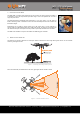
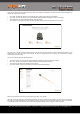
LW20 / SF20 LiDAR sensor Product manual Used on autonomous vehicles, the LW20 can be a forwards looking obstacle sensor or can be used to create “SLAM” maps to aid in navigation. Figure 3 :: Autonomous vehicle navigation What’s your application? 3. What are the main characteristics of the LW20? SF20 LW20 There are two models available, the LW20 and the SF20. The LW20 is a sealed unit suitable for outdoor applications. It can easily be added onto existing products.
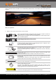
LW20 / SF20 LiDAR sensor Product manual The LW20 is able to measure the first and last return signals when there is more than one object in the laser beam. Measuring the distance to the nearest object and the furthest object allows a drone to get information about potential collisions with trees while simultaneously following the terrain at a known height above ground. Objects must be separated by approximately 5 meters before they are seen as separate return signals.
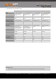
LW20 / SF20 LiDAR sensor Product manual 4. Specifications of the LW20 / SF20 LW20/B (50 m) LW20/C (100 m) SF20/B (50 m) SF20/C (100 m) Weight 20 g (excluding cables) 20 g (excluding cables) 10 g (excluding cables) 10 g (excluding cables) Range 0.2 … 50 m (sunlit white wall, 45 readings per second) 1 cm 0.2 … 100 m (sunlit white wall, 45 readings per second) 1 cm 0.2 … 50 m (sunlit white wall, 45 readings per second) 1 cm 0.
LW20 / SF20 LiDAR sensor Product manual 5. How to communicate with the LW20 using the graphical interface To use the graphical interface to setup and test the LW20 you will need to connect the serial port of the LW20 to the USB port on a PC. This is done using a serial-to-usb converter such as the TTL-232R-3V3-WE converter cable from FTDI (http://www.ftdichip.com/ Products/Cables/USBTTLSerial.htm). This converter provides both the signals and power supply to the LW20.
LW20 / SF20 LiDAR sensor Product manual There are four tabs at the top of the home screen.
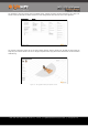
LW20 / SF20 LiDAR sensor Product manual The “Parameters” tab gives a summary of all the available settings, grouped into columns to match the buttons on the “Setup” tab. This tab is useful to users who are familiar with effects of each setting and know what values to enter for their application. Figure 8 :: The graphical interface Parameters screen The “Operate” tab shows a graphic that can be used for display purposes.
LW20 / SF20 LiDAR sensor Product manual 6. How to communicate with the LW20 using a terminal emulator To use a terminal emulation application to setup and test the LW20 you will need to connect the serial port of the LW20 to the USB port on a PC. This is done using a serial-to-usb converter such as the TTL-232R-3V3-WE converter cable from FTDI (http:// www.ftdichip.com/Products/Cables/USBTTLSerial.htm). This converter provides both the signals and power supply to the LW20.
LW20 / SF20 LiDAR sensor Product manual Pressing the key switches the LW20 into human-to-machine mode providing data and menus in an easy to read format. You can navigate between the menus and live data streams using the arrow keys. There are four screens available, two show the LW20 setup and two show the setup of the servo if it is attached.
LW20 / SF20 LiDAR sensor Product manual 6.1 How to communicate with the LW20 using the Devantech USB to I2C module Figure 13 :: Connection to a Devantech USB-ISS module The I2C interface is designed for machine-to-machine communications with multiple devices over a small network. In order to test the I2C interface on the LW20, an I2C to USB converter can be connected and a limited number of commands can be sent to the LW20 using the LightWare Terminal application.
LW20 / SF20 LiDAR sensor Product manual Once the correct setting is applied, commands can be sent and results viewed by selecting the “I2C Tester” icon and pressing the one of the test buttons available in the dialog box. Figure 16 :: I2C test dialog box showing command buttons The factory default I2C bus address is 0x66. LW20 / SF20 LiDAR - Product manual - Revision 9 | 14 of 28 | © LightWare Optoelectronics (Pty) Ltd, 2018 | www.lightware.co.
LW20 / SF20 LiDAR sensor Product manual 7. How to communicate with the LW20 using a controller The LW20 is designed to communicate with a host controller. This controller can be a single board computer, flight controller or a PC. There are two communications interfaces available, serial and I2C. The LW20 will wait for the first command to confirm which communication mode to select (serial or I2C). The first command will not get a response.
LW20 / SF20 LiDAR sensor Product manual 8. How to do an initial setup of the LW20 Using the GUI, Terminal or machine commands the measuring characteristics of the LW20 can be tailored to suit different applications. The primary settings can be found by pressing the “Laser” button under the “Setup” tab of the GUI or on the main menu screen of the terminal. Figure 17 :: Initial setup using the GUI or terminal emulation Details of the initial settings are given in the table below.
LW20 / SF20 LiDAR sensor Product manual 9. How to set up a scanning LiDAR using a digital servo The LW20 can be converted into a scanning LiDAR by attaching it to a digital servo and using the built-in servo driver hardware and software. The LiDAR data can be streamed live or used to activate two internal alarms. This makes a useful SLAM mapping device or a collision sensor. The servo driver works with most standard digital servos.
LW20 / SF20 LiDAR sensor Product manual When viewed from above, the lower PWM setting turns the servo shaft to the extreme left position and the higher PWM setting turns it to the extreme right. The midpoint position corresponds to the PWM value that is halfway between the two end settings. Figure 20 :: Setting the servo’s limits of motion using the PWM values For each degree of motion by the servo, the PWM pulse width needs to change by a specific number of us.
LW20 / SF20 LiDAR sensor Product manual Configuring the scanning motion is done by selecting the “Sweep” button under the “Setup” tab. Note that the settings entered here are limited by the physical and electrical characteristics of the servo. Only the first return signal is shown on the graphic. Figure 22 :: Setting up the servo’s scanning characteristics The speed of the scan is determined by how fast the LW20 updates and the number of steps that the servo moves with each reading.
LW20 / SF20 LiDAR sensor Product manual Changing the field of view does not affect the physical motion of the servo as this would upset the PWM and servo lag settings. Instead, the field of view cuts out unwanted data from the edges of the scanned image. The left and right edge settings of the field of view can be changed independently. Figure 24 :: Reducing the field of view to avoid detecting the landing legs on a drone For high precision scanning, the servo can be made to scan in one direction only.
LW20 / SF20 LiDAR sensor Product manual 10. How to set up the alarms The LW20 has two alarms, A and B, that be can used to warn when objects get too close. The alarm changes from a 0 state to a 1 state when an object is detected closer than the set distance. The alarms are updated every time a new distance measurement is taken. The alarm distances and hysteresis can be set using the “Laser” button found under the “Setup” tab.
LW20 / SF20 LiDAR sensor Product manual 12. Instructions for safe use The LW20 is a laser based altimeter that emits ionizing laser radiation. The level of the laser emission is Class 1M which indicates that the laser beam is safe to look at with the unaided eye but must not be viewed using binoculars or other optical devices at a distance of less than 0.5 meters. Notwithstanding the safety rating, avoid looking into the beam and switch the unit off when working in the area.
LW20 / SF20 LiDAR sensor Product manual Appendix B :: Cables and connections Serial and power cable 40 cm 35 mm Strip and tin 5 mm Twist shield wires 20 mm Part no. 1 2 3 DK: 455-2177-ND Manufacturer part no. JST Sales America 08SUR-32S Daburn 2752/5 DK: 490-11141-ND Murata FSRH044C00RNB00B 2 3 Twist shield wires 1 Description Conn Rcpt 8 Pos 0.8mm Male Sub-Miniature Shielded Cable 32 AWG, black Ferrite Core 40 OHM Solid 1.5mm NOTE: Wire colours are critical. Do not deviate.
LW20 / SF20 LiDAR sensor Product manual Appendix C :: Complete command set for machine-to-machine communications The LW20 has either a serial or an I2C communication port. Commands can be sent that read values, change settings or alter the performance of the LW20. Distances are in meters and temperatures in degrees celsius. Commands are sent and responses received in ASCII format (human readable). These ASCII strings have a maximum of 32 characters.
LW20 / SF20 LiDAR sensor Product manual Command Typical return Description ?LH ?LHF ?LHL lhf:100 lhf:100 lhl:78 Signal strength of first default signal (%) Signal strength of first return (%) Signal strength of last return (%) ?LO #LO,0.56 lo:0.14 lo:0.56 Read distance measurement datum offset Change to a new datum offset: Adjustment range = -10.00 … 10.00 ?LA ?LAA #LAA,5.00 laa:3.00 laa:3.00 laa:5.
LW20 / SF20 LiDAR sensor Product manual Command Typical return Description ?ST #ST,0 st:1 st:0 Read the type of scan being used Change the type of scan: 0 = bidirectional scan 1 = unidirectional scan ?SR #SR,8 sr:4 sr:8 Read the number of servo steps per reading Change the number of servo steps per reading: Adjustment range = 1 … 32 ?SL #SL,2.57 sl:1.32 sl:2.57 Read the servo lag angle in degrees Change the servo lag angle: Adjustment range = 0.00 … 90.00 ?SFL #SFL,-30.0 sfl:-45.0 sfl:-30.
LW20 / SF20 LiDAR sensor Product manual Data streaming The LW20 can stream up to five read commands (?).
LW20 / SF20 LiDAR sensor Product manual Revision history Version Date Author Comments Rev 9 2018/07/23 TLP Included “Figure 30 :: Heat sink contact area” (page 22). Rev 8 2018/07/04 TLP Rev 7 2018/04/26 TLP Rev 6 2018/04/05 TLP Removed feature “Remove feature: “Encoded laser pulses prevent interference for other lasers” (pages 1, 6). Removed feature “Power saving mode to save energy when not in use” (page 1). Updated power supply current to “130 mA” (pages 5, 7).