LW24 LiDAR sensor MicroLiDAR for obstacle detection Disclaimer Information found in this document is used entirely at the reader’s own risk and whilst every effort has been made to ensure its validity, neither LightWare Optoelectronics (Pty) Ltd nor its representatives make any warranties with respect to the accuracy of the information contained herein.
Table of contents Overview 4 Product support 4 Specifications 4 Quickstart guide 5 Package contents The LW24/C box includes: Dimensions Components Optical assembly Heatsink & EMI shield Connectors & indicators Communication cable pinout 10 10 10 11 11 11 12 12 Installation Mounting 13 13 Operating concepts Distance measuring Serial port baud rate Startup mode Update rate Zero distance offset Lost signal threshold Enable median filter Median filter size Enable rolling average filter Rolling avera
Packets Checksum C/C++ JavaScript Receiving packets Handling request & response 20 21 21 22 22 23 I2C interface Overview 24 24 Command list 26 Command descriptions 0. Product name 1. Hardware version 2. Firmware version 3. Serial number 7. UTF8 text message 9. User data 10. Token 12. Save parameters 14. Reset 16. Stage firmware 17. Commit firmware 27. Distance output 30. Stream 44. Distance data in cm 45. Distance data in mm 50. Laser firing 57. Temperature 66. Update Rate 74. Noise 75.
Overview The LW24/C is an IP67 LiDAR sensor designed for applications where communication interfaces Serial and I2C or RS232 are required. The LW24/C LiDAR sensor uses a time-of-flight system to make very fast, accurate distance and speed measurements. The LW24/C LiDAR is effective in most weather conditions, even in direct sunlight. The LW24/C is virtually immune to background light, wind, and noise, making it an ideal sensor to detect unexpected obstacles.
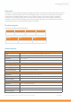
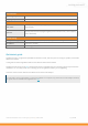
Environmental Operating temperature -10 ... + 50°C / 14 … 122 °F Shipping temperature - 40 … + 80 °C / - 40 … +176 °F Accessories Main cable Tensility International Corp Straight 4 position female to wire, 1.83 m (DigiKey: 839-1553-ND) Tensility International Corp Right-angled 4 position female to wire, 1.
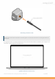
LW24/C being connected to a cable Windows users: Please wait for Windows to install the generic communication driver after connecting the LW24/C for the first time. Run LightWare Studio. You will be presented with a home screen that shows devices connected to your computer. Your USB adaptor will be recognized and displayed here.
You can register your device by clicking on the Register to receive firmware update notifications banner. Click on the USB adaptor to establish a connection. From here you can access tools to inspect and configure the LW24/C. LightWare Studio device information screen Click on the Upgrade tool in the left panel. It is recommended to make sure your LW24/C has the latest firmware. You can see the changes that have been made to each version, and the option of downgrading is also available.
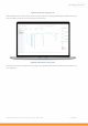
LightWare Studio device upgrade screen. Click the Distance tool in the left panel. This tool shows you distance readings gathered by the LW24/C. Feel free to point the LW24/C at various surfaces to measure their distances. LightWare Studio LW24/C scanning screen. Parameters are shown in the panel on the top right of the LightWare Studio window. Modify these parameters to fit your application.
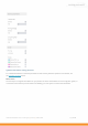
LightWare Studio LW24/C scanning parameters. For a detailed breakdown on what the parameters do and how they affect the operation of the LW24/C, see the operating concepts section. What's next? The next step is to integrate the LW24/C into your platform of choice. Please follow one of the integration guides, or consult the communication protocol reference for building your own system to interact with the LW24/C.
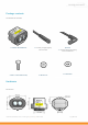
Package contents The LW24/C box includes: 1 x LW24/C MicroLiDAR unit 1 x Tensility straight DigiKey: 839-1553-ND Optional: 1 x Tensility 90 degree DigiKey: 839-10-03635-ND 5 x M2 x 12 Pan slotted screw) 5 x M2 hex nut 5 x Flat washer Hardware Dimensions LW24/C/RS microLiDAR™ sensor - Product guide | Version 0 | 03 March 2022 Page 10 of 38
LW24/C dimensions Components LW24/C view from above and below Optical assembly The optical assembly comprises the laser and receiver lenses. LW24/C optical assembly Heatsink & EMI shield The lid lowers EMI radiation entering or leaving the LW24/C. It also acts as a heatsink to draw heat away from the LW24/C.
LW24/C shield Connectors & indicators LW24/C connectors & indicators Communication cable pinout Communication cable pinout Pin Function Notes 1 +5V 4.5 V … 5.
3 TXD TXD Serial RS232 4 GND Ground Installation Mounting Make sure the LW24/C is functional before installation. You can use LightWare Studio to verify operation. See the quick start with LightWare Studio for details. The LW24/C requires a clear line-of-sight to measure distance to a target surface. It can be mounted with a vertical or horizontal lens orientation.
LW24/C mounting directions Take note: ● Make sure the LW24/C is securely mounted to prevent false readings or damage. ● Allow for proper ventilation. ● Secure the communication cable to prevent it from pulling on the connector. Ensure that nothing is in the path of the laser beam. Ensure that no shiny or highly reflective surfaces are near the path of the beam. Operating concepts Distance measuring The LW24/C is a single point distance measuring LiDAR.
LightWare Studio showing measurements from the LW24/C Parameters LW24/C parameters can be adjusted with LightWare Studio or from the platform of your choice through the serial or I2C communication interfaces.
LightWare Studio parameters screen Serial port baud rate Controls the baud rate used by the serial UART interface in kbps. (The baud rate should be as high as possible to accommodate high measurement update rates.) Startup mode Determines the communication behavior of the LW24/C when turned on. Update rate The number of measurements per second. From 48 Hz to 388 Hz. Zero distance offset An offset applied to the measured distance value.
Enable smoothing filter The smoothing filter is used to remove noise from the measurements. Smoothing filter strength Determines response of the smoothing filter. Firmware change log Upgrading firmware The LW24/C firmware can be upgraded by using LightWare Studio. Download LightWare Studio here. Follow the Quick start with LightWare Studio guide for details on downloading and using LightWare Studio. 2.0.0 Notes: ● Initial release.
Laser eye safety The LW24/C emits ionizing laser radiation. The level of the laser emission is Class 1M which indicates that the laser beam is safe to look at with the unaided eye, but must not be viewed using binoculars or other optical devices. Notwithstanding the safety rating, avoid looking into the beam and switch the unit off when working in the area. The laser eye safety rating depends on the mechanical integrity of the optics and electronics, if these are damaged do not continue using the LW24/C.
Mechanical safety ● Ensure that there is adequate airflow permitted for the sensor. ● The mechanical dimensions for mounting the LW24/C are provided in the hardware overview. Laser radiation information Specification Value/AEL Eye safety classification Class 1M Laser wavelength 905 nm Pulse width 16 ns Pulse frequency 20 kHz Average power < 2.5 mW NOHD 15 m Notes Distance beyond which binoculars may be used safely. Approximate values only.
Serial interface Overview We suggest using the pre-built APIs for communicating with the LW24/C where possible. The LW24/C uses a packet based binary protocol which can be accessed over the serial and I2C interfaces. All higher-level APIs (C, Python, JavaScript) use this protocol to function. If you require more control than the existing APIs offer or need to port the protocol to a different platform, then you can use the information here to build a compatible system.
The Start byte is always 0xAA and indicates the beginning of a packet. It is important to verify that the payload length is between (inclusive) 0 to 1023 and that the checksum is valid before processing a packet, rather than just relying on the start byte. The Flags bytes form a 16 bit integer that represents the payload length and read/write status of the packet. The payload length is inclusive of the ID byte and the required number of data bytes.
} } crc ^= code; return crc; JavaScript function createCRC(data, size) { let crc = 0; for (let i = 0; i < size; ++i) { let code = crc >>> 8 & 0xFF; code ^= data[i] & 0xFF; code ^= code >>> 4; crc = crc << 8 & 0xFFFF; crc ^= code; code = code << 5 & 0xFFFF; crc ^= code; code = code << 7 & 0xFFFF; crc ^= code; } return crc; } Receiving packets Here is the process for reading the raw serial byte stream and identifying packets.
If the packet length or checksum is invalid, then it is technically more correct to roll the incoming stream back to when the start byte was found. However, in practice this has little appreciable impact. Handling request & response Every request sent to the LW24/C will receive a response, it is often useful to use the response to determine if the request was received and processed.
The values used for timeout or number of retries should be tuned to the specific application. I2C interface Overview We suggest using the pre-built APIs for communicating with the LW24/C where possible. The LW24/C uses a packet based binary protocol which can be accessed over the serial and I2C interfaces. All higher-level APIs (C, Python, JavaScript) use this protocol to function.
If you require more control than the existing APIs offer or need to port the protocol to a different platform, then you can use the information here to build a compatible system. The LW24/C will always be the slave on the I2C interface. Therefore, data will only be transmitted when requested by the master. Streaming data is only available through the Serial interface. Requests are made using one of the available commands. When a read request is issued then the response will contain the requested data.
Command list If a command is not readable or writable then it can only be received from the LW24/C and not sent to it.
75 Zero offset This adjusts the zero-distance position in mm RW 4 4 Y 76 Lost signal counter Set number of lost signal conditions RW 4 4 Y 79 Baud rate Serial baud rate RW 1 1 Y 82 Median filter enable Enable/disable the median filter RW 1 1 Y 83 Set median filter size Set the median filter size RW 4 4 Y 84 Smoothing filter enable Enable/disable the median filter RW 1 1 Y 85 Set smoothing filter factor Set the smoothing intensity/factor RW 4 4 Y 93 Rolling a
2. Firmware version The version of currently installed firmware is represented as 4 bytes. This can be used to identify the product for API compatibility. The product support section details which firmware versions this document applies to. 1 2 3 4 Patch Minor Major Reserved Read Write Persists 4 bytes - - 3. Serial number A 16 byte string (null terminated) of the serial identifier assigned during production. Read Write Persists 16 bytes - - 7.
16 bytes 16 bytes Yes 12. Save parameters Several commands write to parameters that can persist across power cycles. These parameters will only persist once the Save parameters command has been written with the appropriate token. The safety token is used to prevent unintentional writes and once a successful save has completed the token will expire. Read Write Persists - uint16 - 14. Reset Writing the safety token to this command will restart the LW24/C. Read Write Persists - uint16 - 16.
-4 Firmware file has invalid header -5 Flash failed to write -6 Firmware is for a different hardware version or firmware version is too low -7 Firmware is for a different product Read Write Persists uint32 130 bytes - 17. Commit firmware The second part of uploading firmware to the LW24/C is to commit the staged data. Once the firmware data has been fully uploaded using the 16. Stage Firmware command, then this command can be written to (with 0 bytes).
1 First return filter 2 First return strength 3 Last return raw 4 Last return filter 5 Last return strength 6 Background noise 7 Temperature Read Write Persists uint32 uint32 No 30. Stream The LW24/C can continuously output data without individual request commands being issued. Reading from the Stream command will indicate what type of data is being streamed. Writing to the Stream command will set the type of data to be streamed. Value Streamed data 0 disabled 5 44.
This command can be read at any time however if 30. Stream is set to 5 then this command will automatically output at the measurement update rate. The data will be packed in order based on the bits set in the Distance output parameter.
Read Write Persists varies - - 50. Laser firing Reading this command will indicate the current laser firing state. Writing to this command will enable or disable the firing of the laser. Value Description 0 Disabled 1 Enabled Read Write Persists uint8 uint8 No 57. Temperature Reading this command will return the temperature in 100ths of a degree. Read Write Persists uint32 - - 66. Update Rate This controls the update rate of the LW24/C.
6 129 7 194 8 388 Read Write Persists uint8 uint8 Yes 74. Noise Reading this command will return the level of background noise. Read Write Persists uint32 - - 75. Zero offset Changing this offset value will change the Zero distance position for the output. This value is written and read in mm. Read Write Persists int32 int32 Yes 76.
1 19200 2 38400 3 57600 4 115200 5 230400 6 460800 7 921600 Read Write Persists uint8 uint8 Yes 82. Median filter enable Reading this command will return the status of the median filter. Writing this command will set the status of the median filter. Value Description 0 disabled 1 enabled Read Write Persists uint8 uint8 Yes 83. Median filter size Reading this command will return the size of the median filter. Writing this command will set the size of the median filter.
84. Smoothing filter enable Reading this command will return the status of the smoothing filter. Writing this command will set the status of the smoothing filter. Value Description 0 disabled 1 enabled Read Write Persists uint8 uint8 Yes 85. Smoothing factor Reading this command will return the strength of the smoothing filter. Writing this command will set the strength of the smoothing filter. The valid range is 0 to 100. Read Write Persists Uint32 Uint32 Yes 93.
The valid range is 2 to 32.
Document revision Revision Date Comments Rev 0 2022/03/03 First edition LW24/C/RS microLiDAR™ sensor - Product guide | Version 0 | 03 March 2022 Page 38 of 38