
User's Manual

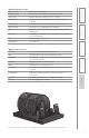

8
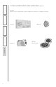
1. Overview
2. Set Up & Use /
Daily Operation
3. Optional Accessories
4. Maintenance &
Troubleshooting
5. Warranty, Safety
& Specifications
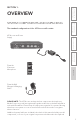
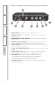
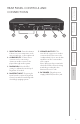
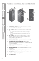
FRONT PANEL CONTROLS & INDICATORS
AUDIO INMICROPHONE TONE
POWER
MIN
1
MAX MIN MAX TREBLE BASS
2
AUDIO OUT
MIN MAX
1. POWER LIGHT: This light will turn blue when power is on.
2. POWER BUTTON: Press and hold this push button to turn the system
power on or off.
3. MICROPHONE VOLUME CONTROL: Controls the volume level of the
microphones.
4. AUDIO IN VOLUME CONTROL: Controls the volume level of the audio
sources connected to the audio inputs on back of the 955 Access.
5. TONE CONTROL: Adjusts the audio tone adding more bass or treble for
a more rich or more crisp tone.
6. AUDIO OUT VOLUME CONTROL: Controls the volume level of the audio
output
7. AUDIO OUTPUT JACK: 3.5mm stereo connector for connecting to an
assisted listening device (ALD) or to a computer for recording.
8. MIC 1 & MIC 2: Microphone link and registration indicators.
a. Solid green indicates an audio link has been established.
b. Flashing amber indicates registration is in process.
9. SYSTEM ID LABEL: On bottom of unit (not shown) to identify it with
registered components.
5
1
2
4
2
3
9
2
8
6
2
7