RE-82 RACK MOUNT DIMMER 8 X 2400Watts OWNERS MANUAL Revision 2.4 11/29/2007 www.lightronics.
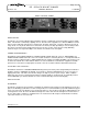
Page 2 of 8 RE - 82 RACK MOUNT DIMMER Revision 2.4 OWNERS MANUAL 11/29/2007 RE-82 CONTROL PANEL DESCRIPTION The RE-82 is an 8 channel dimmer with a maximum capacity of 2,400 watts per channel giving a total of 19,200 watts. The RE-82 is controlled by a lighting console. The unit can be supplied to use either the DMX-512 control protocol or the LMX-128 control protocol. Channels A - D and/or channels E - H may be switched to operate in "relay" mode.
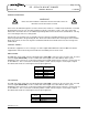
Page 3 of 8 RE - 82 RACK MOUNT DIMMER OWNERS MANUAL Revision 2.4 11/29/2007 POWER CONNECTIONS WARNING MAKE CERTAIN POWER IS REMOVED FROM THE FEED CIRCUITS BEFORE YOU BEGIN INSTALLATION. Power enters the RE-82 through the rear of the unit via a hole sized for 1" conduit. Inside the RE-82 is a terminal block with three lugs. The "H1" and "H2" terminals are the line connections or "hots". The center connection labeled "N" is the neutral.
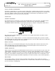
Page 4 of 8 RE - 82 RACK MOUNT DIMMER OWNERS MANUAL Revision 2.4 11/29/2007 OUTPUT CHANNEL CONNECTIONS The RE-82 is supplied with one of several rear panel output options. Channel output connections are according to the the rear panel selected. Channel connections generally proceed from left to right (if you are facing the rear of the unit). Channel “A” will be on the left end. Connections for load Neutrals are provided. There is also a ground lug terminal to be used for your load circuits grounds.
Page 5 of 8 RE - 82 RACK MOUNT DIMMER OWNERS MANUAL Revision 2.4 11/29/2007 MAINTENANCE AND REPAIR CIRCUIT BREAKERS AND FUSES Each channel of the RE-82 is protected by a 20 Amp, fast acting, magnetic circuit breaker located on the front panel of the unit. If the total load for a channel is greater than 2400 Watts the channel circuit breaker will trip. There are two 1/2 Amp., 250 Volt, fast acting fuses on the front panel to protect the internal electronic circuits from an overvoltage condition.
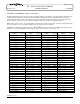
Page 6 of 8 RE - 82 RACK MOUNT DIMMER OWNERS MANUAL Revision 2.4 11/29/2007 CHANNEL ASSIGNMENT SWITCH SETTINGS The DIP Switch Setting column shows the positions of the DIP switches on the dimmer. The Start Channel column shows the resulting channel assignment for the first channel of the dimmer All Lightronics products using DIP switches for address assignments conform to this table. Some dimmers cannot be set to all 512 channels and will have fewer switches than are shown in the table.
WARRANTY All Lightronics products are warranted for a period of TWO/FIVE YEARS from the date of purchase against defects in materials and workmanship. This warranty is subject to the following restrictions and conditions: A) If service is required, you may be asked to provide proof of purchase from an authorized Lightronics dealer.
www.lightronics.