RA - 122 RACK MOUNT ARCHITECTURAL DIMMER OWNERS MANUAL Version 0.93 09/26/2011 www.lightronics.com Lightronics Inc.
Page 2 of 20 RA – 122 RACK MOUNT ARCHITECTURAL DIMMER Revision 0.
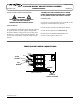
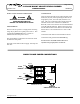
Page 3 of 20 RA – 122 RACK MOUNT ARCHITECTURAL DIMMER OWNERS MANUAL Revision 0.93 09/26/2011 RA-122 UNIT DESCRIPTION POWER REQUIREMENTS The RA-122 consists of a processor and 12 dimmer channels of 2.4KW each. Each dimmer channel is protected by a 20 Amp circuit breaker. Heavy duty filtering chokes are used to reduce noise. Dimmer channel semiconductors exceed a 200% load carrying capacity overhead allowance. The RA-122 may be controllad by DMX controllers and several types of wall remote stations.
Page 4 of 20 RA – 122 RACK MOUNT ARCHITECTURAL DIMMER OWNERS MANUAL Revision 0.93 THREE PHASE POWER CONNECTIONS WARNING MAKE CERTAIN POWER IS REMOVED FROM THE FEED CIRCUITS BEFORE YOU BEGIN INSTALLATION. REQUIREMENTS 09/26/2011 THE UNIT WILL NOT OPERATE IN IT'S THREE PHASE CONFIGURATION USING ONLY 2 LINES OF A 3 PHASE 120/208 VAC SUPPLY CIRCUIT. CONNECTIONS Connect the 3 in hot feed lines to the 3 terminals on the input power terminal block (H1, H2, H3).
Page 5 of 20 RA – 122 RACK MOUNT ARCHITECTURAL DIMMER OWNERS MANUAL Revision 0.93 SINGLE PHASE POWER CONNECTIONS WARNING MAKE CERTAIN POWER IS REMOVED FROM THE FEED CIRCUITS BEFORE YOU BEGIN INSTALLATION. REQUIREMENTS The RA-122 can operate as a single phase unit using using only 2 phases of a 3 phase power source. This is NOT RECOMMENDED since it causes an unbalanced load to the power source. The unit should be connected to two hot lines which are NOT the same phase.
Page 6 of 20 RA – 122 RACK MOUNT ARCHITECTURAL DIMMER OWNERS MANUAL Revision 0.93 LOAD CONNECTIONS 09/26/2011 One of the connectors is used for control signal input, the other is to pass the control signals to another RA122. The connectors are "hardwired" together so either one can be used for "in" or "out". The RA-122 is supplied with one of several different rear load connection panels.
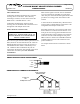
Page 7 of 20 RA – 122 RACK MOUNT ARCHITECTURAL DIMMER OWNERS MANUAL Revision 0.93 DMX TERMINATION A DMX bus should be terminated (only) at the last receiving device on the chain. This is done by connecting a 120 ohm, 1/4 watt resistor across the DMX DATA - and DMX DATA + lines. 09/26/2011 Smart remote signals to the RA-122 are transmitted over a two twisted pair, shielded, low capacitance cable. One pair carries the RS-485 signal and the other provides a low voltage power and common to the remotes.
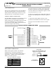
Page 8 of 20 RA – 122 RACK MOUNT ARCHITECTURAL DIMMER Revision 0.93 OWNERS MANUAL SIMPLE REMOTES CONNECTIONS CAUTION REMOVE ALL POWER FROM THE RA-122 BEFORE MAKING OR CHANGING SIMPLE REMOTE CONNECTIONS. Scenes 1 - 7 (stored in the RA-122) may be accessed by simple remotes. A BLACKOUT FUNCTION may also be accessed. A simple remote is any switch which can provide a momentary contact closure that can be applied to a specific pin on the RA-122 CONTROL SIGNALS CONNECTOR (DB25 connector).
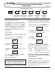
Page 9 of 20 RA – 122 RACK MOUNT ARCHITECTURAL DIMMER OWNERS MANUAL Revision 0.93 09/26/2011 TOP LEVEL MENUS LAYOUT MENU (NEXT) D SCENE SETUP MENU (NEXT) EVENT SETUP MENU (NEXT) ENTER ENTER Create and Edit Internal Scenes Set Clock and Timed Events USING THE MENU SYSTEM The CONFIG button steps through the five display menus. When one of these menus is shown you can push ENTER to access that function.
Page 10 of 20 RA – 122 RACK MOUNT ARCHITECTURAL DIMMER OWNERS MANUAL Revision 0.93 At the RA-122 front panel - push CONFIG until the System Setup appears on the status display. 09/26/2011 CHANNEL NON-DIM (RELAY) MODE To set a channel to Non-Dim: Push CONFIG until the Dimmer Setup menu appears on the display. SYSTEM SETUP Push ENTER. Then push CONFIG. The System ID Set menu will be shown. SYSTEM ID SET DIMMER SETUP Push ENTER. Then push CONFIG.
Page 11 of 20 RA – 122 RACK MOUNT ARCHITECTURAL DIMMER OWNERS MANUAL Revision 0.93 CONSOLE LOCKOUT: You can set any dimmer channel output to ignore DMX signal inputs from a DMX console by assigning it to DMX channel 000. This feature can be used with house lights or other special lighting. The channel will still respond to wall remotes but the DMX console will be ignored.
Page 12 of 20 RA – 122 RACK MOUNT ARCHITECTURAL DIMMER OWNERS MANUAL Revision 0.93 TO COPY A SCENE 09/26/2011 Push ENTER when COPY SCENE is shown. The display will show a menu so you can select an existing scene to copy from. The procedure is similar to that for other scenes except the blackout fade time is accessed by selecting SCENE 00 from the SCENE SETUP menu. Factory default fade time is 3 seconds. Blackout fade time may be set between 0.5 and 99.5 seconds.
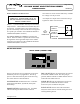
Page 13 of 20 RA – 122 RACK MOUNT ARCHITECTURAL DIMMER OWNERS MANUAL Revision 0.93 Channel Intensity Bar Graph 1 2 3 4 5 6 7 8 D 9 10 11 12 Valid DMX indication SMART REMOTES OPERATION The RA-122 can store 100 preset scenes which may be activated by smart remotes. See the section "Creating and Editing Scenes" for info about programming the scenes. These scenes are grouped according to which type of smart remote can access them. Scenes 1 - 48 are reserved for push button and IR remotes.
Page 14 of 20 RA – 122 RACK MOUNT ARCHITECTURAL DIMMER OWNERS MANUAL Revision 0.93 09/26/2011 EVENT SYSTEM OPERATION SETTING THE INTERNAL CLOCK The RA-122 includes an internal clock and timer sub system. This subsystem may be used to create events which activate and switch between preset lighting scenes based upon times, days, and dates. A total of 128 events may be programmed. The clock must be set to the correct date, time and day of the week in order to operate correctly.
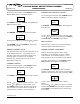
Page 15 of 20 RA – 122 RACK MOUNT ARCHITECTURAL DIMMER OWNERS MANUAL Revision 0.93 A complete layout diagram of the menus for setting the clock is shown below. EVENT SETUP MENU (NEXT) 09/26/2011 The complete event editor menus layout is shown below.
Page 16 of 20 RA – 122 RACK MOUNT ARCHITECTURAL DIMMER OWNERS MANUAL Revision 0.93 09/26/2011 SELECTING AN EVENT SETTING DATE BASED TRIGGERS From the EVENT EDITOR menu - Push ENTER. The display will show the event selection menu as follows. The top row of these menus show the event and scene number you are working on. If an event already has a scene assigned to it then the event number will be followed by an asterisk (*). To set the date: Use the and buttons to select the event number.
Page 17 of 20 RA – 122 RACK MOUNT ARCHITECTURAL DIMMER OWNERS MANUAL Revision 0.93 09/26/2011 Push CONFIG to proceed with setting the trigger time or push CLEAR to revert to the event number selection menu. To set the trigger time: E001S000 00:00 Use the and buttons to select hours or minutes. Your selection is indicated by flashing that part of the menu. The format for hours is 0 - 23 (not AM/PM). Use the and buttons to change the value. Push ENTER once a value has been selected.
Page 18 of 20 RA – 122 RACK MOUNT ARCHITECTURAL DIMMER OWNERS MANUAL Revision 0.93 09/26/2011 MAINTENANCE AND REPAIR WARNING MAKE CERTAIN POWER IS REMOVED FROM THE FEED CIRCUITS BEFORE HANDLING THE UNIT. TROUBLESHOOTING To simplify troubleshooting - reset the unit or provide a known simple set of conditions. Check that the console is powered and that console channels are correctly patched or set. Check the control cable between the dimmer(s) and console.
WARRANTY All Lightronics products are warranted for a period of TWO/FIVE YEARS from the date of purchase against defects in materials and workmanship. This warranty is subject to the following restrictions and conditions: A) If service is required, you may be asked to provide proof of purchase from an authorized Lightronics dealer.
www.lightronics.com Lightronics Inc.