RTC ARCHITECTURAL SERIES AR - 1202RTC 12 CHANNEL X 2.4KW ARCHITECTURAL DIMMER OWNERS MANUAL Revision 1.93 06/03/2008 www.lightronics.com Lightronics Inc.
Page 2 of 22 AR – 1202RTC ARCHITECTURAL DIMMER Revision 1.
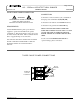
Page 3 of 22 AR – 1202RTC ARCHITECTURAL DIMMER Revision 1.93 OWNERS MANUAL 06/03/2008 AR-1202 UNIT DESCRIPTION POWER REQUIREMENTS The AR-1202 consists of an embedded micro processor and 12 dimmer channels of 2.4KW each. Each dimmer channel is protected by a 20 Amp circuit breaker. Heavy duty filtering chokes are used to reduce noise. Dimmer channel semiconductors exceed a 200% load carrying capacity overhead allowance. All components and sub systems are UL recognized components.
Page 4 of 22 AR – 1202RTC ARCHITECTURAL DIMMER Revision 1.93 OWNERS MANUAL 06/03/2008 THREE PHASE POWER CONNECTIONS CONNECTIONS WARNING MAKE CERTAIN POWER IS REMOVED FROM THE FEED CIRCUITS BEFORE YOU BEGIN INSTALLATION. Connect the 3 in hot feed lines to the 3 terminals on the input power terminal block (H1, H2, H3). Connect the feed neutral to the NEUTRAL bus bar. Connect the feed ground to the GROUND lug.
Page 5 of 22 AR – 1202RTC ARCHITECTURAL DIMMER Revision 1.93 OWNERS MANUAL SINGLE PHASE POWER CONNECTIONS WARNING MAKE CERTAIN POWER IS REMOVED FROM THE FEED CIRCUITS BEFORE YOU BEGIN INSTALLATION. REQUIREMENTS The RA-122 can operate as a single phase unit using using only 2 phases of a 3 phase power source. This is NOT RECOMMENDED since it causes an unbalanced load at the power source. The feed circuit must be able to supply 120 Amps for each line.
Page 6 of 22 AR – 1202RTC ARCHITECTURAL DIMMER Revision 1.
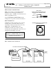
Page 7 of 22 AR – 1202RTC ARCHITECTURAL DIMMER Revision 1.93 OWNERS MANUAL 06/03/2008 DMX CONSOLE CONNECTIONS DMX CABLE CONDUCTOR ARRANGEMENT FOR TWISTED PAIR, SHIELDED CABLE DMX console signals to the AR-1202 should be transmitted over a twisted pair, shielded, low capacitance cable. A DMX console transmits from a female, 5 Pin XLR Connector. Common Shield DMX Data DMX Data + See the EXTERNAL CONNECTIONS and the example below for specific connection information.
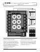
Page 8 of 22 AR – 1202RTC ARCHITECTURAL DIMMER Revision 1.93 OWNERS MANUAL 06/03/2008 SMART REMOTE CONNECTIONS There are two types of smart remotes (push button and fader) which can be used with the AR-1202. There are multiple models of each type. They all connect to a common RS-485 bus which is controlled by a AR1202. Additional AR-1202 dimmers may also be connected on the same bus. One of them will be set as the master controller by making UNIT ADDRESS ASSIGNMENTS.
Page 9 of 22 AR – 1202RTC ARCHITECTURAL DIMMER Revision 1.93 OWNERS MANUAL 06/03/2008 SIMPLE REMOTE CONNECTIONS When the switch is operated the closure brings the common back to the applicable simple remote scene number connection point at the AR-1202 terminal strip. Almost any available low voltage wire may be used since these connections are just contact closures. CAUTION REMOVE ALL POWER FROM THE AR-1202 BEFORE MAKING OR CHANGING SIMPLE REMOTE CONNECTIONS.
Page 10 of 22 AR – 1202RTC ARCHITECTURAL DIMMER Revision 1.93 OWNERS MANUAL 06/03/2008 AR-1202 UNIT SETUP The AR-1202 must be set up (configured) as part of the installation process. This process is done from the AR-1202 front panel using 5 menus described below. SYSTEM SETUP should be done first. It includes: setting the System Mode, System ID, and System Power Setup. DMX I/O SETUP must be performed if the unit will be used with a DMX console.
Page 11 of 22 AR – 1202RTC ARCHITECTURAL DIMMER Revision 1.93 OWNERS MANUAL Push ENTER. Then push MENU (NEXT) until the System Power menu appears on the status display. At the AR-1202 front panel - push MENU (NEXT) until the System Setup appears on the status display. SYSTEM POWER SYSTEM SETUP Push ENTER. The display will show the current power configuration. For example: Push ENTER. Then push MENU (NEXT). The System ID Set menu will be shown.
Page 12 of 22 AR – 1202RTC ARCHITECTURAL DIMMER Revision 1.93 OWNERS MANUAL CHANNEL NON-DIM (RELAY) MODE To set a channel to Non-Dim: Push MENU (NEXT) until the Dimmer Setup menu appears on the display. DIMMER SETUP 06/03/2008 CONSOLE LOCKOUT: You can set any dimmer channel output to ignore DMX signal inputs from a DMX console by assigning it to DMX channel 0. This feature can be used with house lights or other special lighting.
Page 13 of 22 AR – 1202RTC ARCHITECTURAL DIMMER Revision 1.93 OWNERS MANUAL There are three ways to create or set up a scene: 1. Set each channel intensity manually (EDIT SCENE) 2. Copy another existing scene (COPY SCENE). You can then edit the results. 3. Record a snapshot of the current channel intensities (RECORD LIVE NOW) Push MENU (NEXT) to select one of the 3 methods described above. The display will show the corresponding menu. TO CREATE A SCENE MANUALLY Push ENTER when EDIT SCENE is shown.
Page 14 of 22 AR – 1202RTC ARCHITECTURAL DIMMER Revision 1.93 OWNERS MANUAL 06/03/2008 SCENE BLACKOUT FADE TIME SMART REMOTES OPERATION Fade time for the remote stations blackout function is set as an independent function. The procedure is similar to that for other scenes except the blackout fade time is accessed by selecting SCENE 00 from the SCENE SETUP menu. Factory default fade time is 3 seconds. Blackout fade time may be set between 0.5 and 99.5 seconds.
Page 15 of 22 AR – 1202RTC ARCHITECTURAL DIMMER Revision 1.93 OWNERS MANUAL Currently available fader remotes are the AF-2004, AF-3007 and the AF-5013. Fader remotes are scene block addressable so you can select which scenes will be activated it. There are 3 scene blocks available. Each block includes 16 scenes. The first block starts at scene 51. This refers to the lowest numbered fader on the remote. The other faders on that remote will use the next consecutively numbered scenes (52, 53, 54, etc.).
Page 16 of 22 AR – 1202RTC ARCHITECTURAL DIMMER Revision 1.93 OWNERS MANUAL Push MENU (NEXT) to proceed to the Set Day menu. 06/03/2008 event times and dates but they will never be triggered. Turning events OFF is used to prevent triggers which may have been forgotten about, incorrectly set, or otherwise unaccounted for. SET DAY MONDAY SETTING THE DAY OF THE WEEK TO CONTROL EVENT TRIGGERING The day of the week MUST BE SET when setting or changing the date.
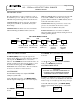
Page 17 of 22 AR – 1202RTC ARCHITECTURAL DIMMER Revision 1.93 OWNERS MANUAL Programming an event consists of four steps: 1. Select the event you want to set up (1 - 128). 2. Assign a scene (1 - 100) to the event. 3. Select what action is to be performed for that scene (Turn it ON, Turn it OFF, or IGNORE IT). 4. Assign the DATE/ TIME or DAY(S) / TIME for the event to be triggered. E001S000 DATE 06/03/2008 OR E001S000 DAYS The top row shows the event number and scene number you are working on.
Page 18 of 22 AR – 1202RTC ARCHITECTURAL DIMMER Revision 1.93 OWNERS MANUAL MAINTENANCE AND REPAIR To set days of the week: E001S000 SMTWTFS OWNER MAINTENANCE The bottom menu row shows the days. If a day shows as a solid block ( ) instead of a character then the event will be skipped (will not trigger on that day). Use the and buttons to select a week day. Then use the and buttons to change between trigger and skip. Push ENTER once a value has been selected.
Page 19 of 22 AR – 1202RTC ARCHITECTURAL DIMMER Revision 1.
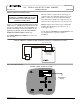
Page 20 of 22 AR – 1202RTC ARCHITECTURAL DIMMER Revision 1.93 OWNERS MANUAL 06/03/2008 DIMENSIONS AND MOUNTING Cabinet Front View With Door Removed 20 1/4” 17 5/8” 16” K K M M CONTROL SIGNAL CONNECTIONS AREA 21 1/8” 18 5/8” POWER CONNECTIONS AREA M M K NOTES: Dimensions are +/- 1/16”. This drawing is not to scale. Cabinet Clearance Depth is 6 1/4" Mounting holes indicated by “M” will accommodate 1/4" bolt. Double 1/2, 3/4 inch knockout holes provided at locations indicated by “K”.
Page 21 of 22 AR – 1202RTC ARCHITECTURAL DIMMER Revision 1.93 OWNERS MANUAL 06/03/2008 AR-1202 UNIT SPECIFICATIONS CHANNELS/CAPACITY: 12 Channels @ 2400 Watts each channel POWER REQUIREMENTS: 120/208VAC three phase,80 Amps each line OR 120/240VAC single phase, 120 Amps each line POWER DEVICES: Dual 65 Amp SCRs POWER CONNECTOR: Terminal strip CHANNEL OUTPUT: Terminal Strip CIRCUIT BREAKERS: 20 Amp fast acting MINIMUM LOAD: 15 Watts CURVE: Modified square law FILTER RISE TIME: 600 usec.
WARRANTY All Lightronics products are warranted for a period of TWO/FIVE YEARS from the date of purchase against defects in materials and workmanship. This warranty is subject to the following restrictions and conditions: A) If service is required, you may be asked to provide proof of purchase from an authorized Lightronics dealer.