
Installation Guide

3
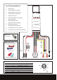
T-taps for wires
3.
Black
Fig 3. Connectors for
non-standard installations
Fig 2. Screw
for xing relay
Insulated male spade terminals
4.
Red
1.
2.
10.
Yellow
9.
5.
Brown
7.
Green
8.
Red
6.
Blue
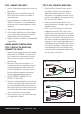
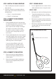
Fig 4. 8 Pin connector wiring diagram (switches side)
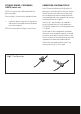
Fig 1. Driving Light Harness
1. 40 Amp Relay
2. Driving light 4 pin connectors
3. Battery negative ring terminal
4. Battery positive ring terminal
5. Ignition pickup wire
6. Low beam pickup wire with bullet
terminal (positive)
7. High beam pickup wire
with bullet terminal (negative)
8. High beam pickup wire
with bullet terminal (positive)
9. Dashboard switch loom connector
10. Dash illumination cable (tment optional).
1.
2.
3.
4.
5.
6.
7.
8.
1 Yellow Dash Illumination (from park lights)
2 Black Negative
3 Blue Switch to Output - to relay trigger
4 Red Switch 2 Input - from high beam positive
5 White Switch 1 Output - driving lights
6 Green Switch 1 Input - from vehicle ignition
7 Not Used N/A
8 Not Used N/A