USER INSTRUCTIONS TRIPLE SWITCHING HIGH POWERED HARNESS FOR GENESIS AND VENOM LED LIGHTS (with positioning light functions) 1
DIY HARNESS INSTALLATION KIT CONTENTS • 1 x Driving light harness • 1 x H4 patch harness • 1 x Switch loom (dual switches) • 1 x Screw for relay installation • 2 x T-taps for wires (2 sizes) • 4 x Spade terminals (2 sizes) • 15 x Cable ties • 1 x User instructions. TOOLS AND CONSUMABLES REQUIRED • Spanner • Pointy nose pliers • Wire cutters • Phillips head driver bit • Flashlight (recommended) • Torque wrench (recommended). TOOL REQUIRED FOR NON-STANDARD INSTALLATIONS Crimping tool.
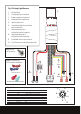
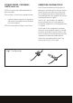
Fig 1. Driving Light Harness 1. 1. 40 Amp Relay 2. Driving light 4 pin connectors 3. Battery negative ring terminal 4. Battery positive ring terminal 5. Ignition pickup wire 6. Low beam pickup wire with bullet terminal (positive) 7. High beam pickup wire with bullet terminal (negative) 8. High beam pickup wire with bullet terminal (positive) 9. Dashboard switch loom connector 10. Dash illumination cable (fitment optional). Fig 2. Screw for fixing relay 6. Fig 3.
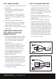
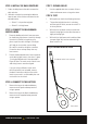
STEP 1. MOUNT THE LIGHTS STEP 3. FULL INTENSITY MODE ONLY 1. Locate a suitable mounting position to install the driving lights. 1. Select the HB3 or H4 patch harness (refer to your vehicle’s owner’s manual and figures 5 and 6 below to determine which is correct) and connect it to a headlight connector on your vehicle. If your headlights are a type other than HB3 or H4, see item 3 below. 2. Remove the nyloc nut and M10 washer from M10 x 35mm bolt attached to the bottom of mounting bracket 3.
OPTIONAL WIRING - POSITIONING LIGHTS (switch one) NOTE: This function will enable and disable the positioning lights . Refer to figure 1 for wire colours and identification 1. Locate the ignition signal wire in your vehicle and connect to the spade terminal (#5) brown wire (refer to figure 1) NOTE: Ensure the ignition voltage is over 10 volts. CONNECTING LOW BEAM PICK UP For H4: Connect the blue wire (No.6) on the H4 path harness to the blue wire on the main harness.
STEP 4. INSTALL THE DASH SWITCHES STEP 7. SECURE CABLES 1. Find a suitable place on the dash to mount the dash switches. 1. 2. Affix dash switches by removing the adhesive from the rear of the switches and attach to the desired location. • Switch 1 is for positioning lights STEP 8. TEST 1. With ignition on check the following functions: • The positioning light function is activating with the ignition switch, ensure the switch 1 is in the on position.