
Manual

All logos and images are subject to relevant trademark and copyright protection LIGHTFORCE Pty Ltd | © June 2016 • Data and specications contained maybe subject to change without notice.
LIGHTFORCE Australia Pty Ltd shall not be liable for damage, malfunction, failure resulting from accident, misuse, misapplication, unauthorised repair, neglect, modication, unauthorised or non standard replacement parts,
accessories, bulbs, batteries or voltage or operation of the product beyond its technical and or environmental specication.
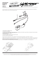
The LED Light bars come complete with a full wiring harness incorporating a 40 amp relay fully terminated two pin waterproof
Deutsch connector, inline fuse and illuminated switch.
1. Mount light in a suitable position
2. Fit relay in a dry location
3. Connect the red ring terminal to the positive side of the battery and the black ring terminal to the negative side of the battery
4. Connect red wire from switch to high beam circuit
5. Position switch in a dry location
6. Run cables to light
7. Fit two pin waterproof Deutsch plug to socket on light
8. Ensure all cable are securely tted
Some automotive manufacturers use the negative circuit to activate the high beam. In this situation, unplug A
(black wire with the open ring) from B (blue wire). A is not used and remains disconnected. Plug C (red wire) into B (blue wire).
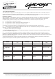
Stainless Steel brackets are included with all bars, the single row bars have a left and a right hand side bracket (Lightforce logo
faces out) and cannot be interchanged, as shown in Fig 1.
The dual row bars have reversible brackets so the bracket can be facing in or out dependent on mounting options.
C
B
A
INSTRUCTION DATA
LED LIGHT BAR
VERSION 1.3
JUNE 2016