
Installation Guide
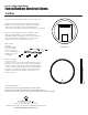

2. Using a le
vel,
mark off a horizon
tal
line, and ensure
t
hat the ends of the brackets are spaced to the width
between the
inner edges of the
vertical aluminium
extrusions (see
illustration 1). Mark off the holes using a pencil.
3.
N
ote: Screws supplied are only suitable for stud
w
alls. For drywall walls use special wall fasteners,
available from DIY or hardware stores. Seek advice fr
om
a specialis
t about the suitability of screws t
o be used.
Dr
ill the required holes and insert wall screws.
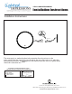
4.
Scr
ew t
he
bracket to
t
he wall using t
he
scr
ews pro
vided.
Please ensur
e t
he
scr
ews are full
y tight
but t
ake care not t
o
o
vertighten.
5. Befor
e mak
ing
an
y electrical con-
nections it is necessary to turn off the main electricity sup-
ply. This unit is provided with a supply cable already fit-
ted. This cable should be fitted to the household lighting
circuit or to a fused 3 AMP supply. Connections should
be made in accordance with the latest regulations. This
cabinet is manufactured to CLASS 1 and requires an
earth connection.
Illus
tration 1
Example 2
C
D
Release Leve
Magnet
Storage
Bar
Release Lever
OPER
ATING INSTRUCTIONS
125 Rt. 61 Schuylkill Haven, PA 17972
1-800-360-1585 • fax 570-385-5475 • info@ltlhomeproducts.com
www.ltlhomeproducts.com
1. Remove the packaging careully, do not lose the screws
LED ILLUMINATED MIRROR
Installation Instructions
Carlton
Press the touch sensor to control the LED light to controlthe on/off and
Keep pressing the touch sensor to control the brightness from bright to dark, or from dark to bright.
change the color temperature through the cycle of "on-4000K-6000K-3000K-off ".