
Installation Guide
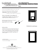

2. Using a level,
mark off a horizon
tal
line, and ensure
that the ends of the brackets are
spaced to the width
between the
inner edges of the
vertical aluminium
extrusions (see
illustration 1). Mark off the holes using a pencil.
3. Note: Screws supplied are only suitable for stud
walls. For drywall walls use special wall fasteners,
available from DIY or hardware stores. Seek advice from
a specialist about the suitability of screws to be used.
Drill the required holes and insert wall screws.
5. Before making
any electrical con-
nections it is necessary to turn off the main electricity sup-
ply. This unit is provided with a supply cable already fit-
ted. This cable should be fitted to the household lighting
circuit or to a fused 3 AMP supply. Connections should
be made in accordance with the latest regulations. This
cabinet is manufactured to CLASS 1 and requires an
earth connection.
Illustration 1
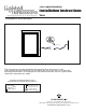
Example 2
C
D
Release Leve
Magnet
Storage
Bar
Release Lever
Example
125 Rt. 61 Schuylkill Haven, PA 17972
1-800-360-1585 • fax 570-385-5475 • info@ltlhomeproducts.com
www.ltlhomeproducts.com
4.Measuring the distance between hanging holes
by using using the screws provide.
Please ensure the screws are fully
tight but take care not to over tighten
OPERATING INSTRUCTIONS
Light can be controlled by using the 3-way rocker under the mirror
to control warm-off-cold of lighting
Portrait or Landscape
1. Remove the packaging careully,
do not lose the screws
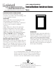
Installation Instructions
LED ILLUMINATED MIRROR
Vero