Instruction Manual
Important Notice TABLE OF CONTENTS Important Notice 1 Front view 2 Function descriptions 5 Settings and adjustments 7 Source feature 11 Installation Guide 15 An LCD panel and/or video monitor may be installed in a motor vehicle and visible to the driver if the LCD panel or video monitor is used for vehicle information , system control , rear or side observation or navigation .
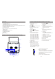
CONTROLS AND INDICATORS DIAGRAM (FRONT VIEW) FEATURES 10 ” TFT LCD (TFT) monitor Built-in DVD Player Selectable(M1 and M2) IR Receive and Transmit Codes Multi-Lingual OSD (On Screen Display) for Control of Picture Quality and Functions Audio\Video Source Inputs Dome Lights with Built-in Three Way Switch Last Memory for DVD Built-in 16 Channel Frequency Wireless FM Modulator EARphone Jack Screen Mode Selection(16:9 , 4:3) Backlit Controls Day\Night Picture Modes AV\Output USB/SD support CONTROLS AND INDICA
CONTROLS AND INDICATORS DIAGRAM (FRONT VIEW) Function descriptions 30 29 1 28 1 2 3 2 2 27 26 1 1 DISC indicator light 2 DVD Disc insertion slot 1 REMOTE CONTROL WINDOW 2. AV IN Jack 3. Headphone Jack 3 4 5 6 25 24 23 22 7 21 20 8 9 10 11 12 19 18 17 16 13 15 14 Remote CONTROL OPERATION 1: POWER Button press this button to turn the unit ON and OFF 2:NUMBER Button Allow the user to enter numbers 0to 9 for selection of selection of CD tracks , DVD chapters , password setting / 3 PREVIOUS\CUR
Function descriptions Function descriptions 9 A B Allow user repeat the playback from point A to point B . Once Repeat A- Mark the beginning of the section to repeat ( Set point A ) Twice Repeat AB Mark the end of the section repeat (Set point B) 3 times AB off Cancel the A-B repeat function . 10 REPEAT Allows the user to repeat a selected title , chapter , or track . For MP3 disc, press “repeat” to repeat playing present file; press it again to repeat playing the folder .
SYSTEM SETUP SYSTEM SETUP Press “Setup” button, the main menu will be displayed on the screen. In the General Setup Page, press button to highlight this item. Press OK button to access. Press button to select the settings. Press OK button to confirm your selection. Press button to exit. OSD Language In this option, user can set OSD menu language. The default is English. Screen Saver Enter this option to set whether to activate the screen saver function. The default is ON.
PLAYING JPG FILES SYSTEM SETUP Disc Menu This function allows you to choose the menu language stored on the disc. The default is English. The function is only available for DVD. Parental Enter this option, user can set child lock to prevent children watching some unsuitable content in DVD disc. The function is disc-dependent. The default is ADULT. Default Select this item and press OK button to reset all settings to the original factory settings. 1. 2. 3. 4.
SOURCE FEATURE TROUBLE SHOOTING PROBLEM IR remote inoperative DVD AV1 USB SD DVD When a disc is loading to the DVD player, the program system will switch to DVD mode directly whatever the CARD or USB and AV is in play condition. Last Memory for the DVD mode: Every time turning power on, it will play from the point stopped last time. At power OFF mode, put into a disc, and it can automatically slot in the disc and turn power on.
SPECIFICATIONS Type : TFT Active Matrix LCD Pixels :800x480 Operation Temperature : 0 ~ 55°C Storage Temperature : -20 ~ 70°C Back light : LED Power Source : DC12V Video Display System : NTSC/PAL Headphone Audio Output : 0.05W @ 32 ohms Video Output : 1.0Vpp@ 75 ohms FCC STATEMENT 1. This device complies with Part 15 of the FCC Rules.
MATERIALS INCLUDED IN THIS PACKAGE 1) 2) 3) 4) 5) 10” LCD Overhead Monitor with DVD play-(1 PCS) 6 Pin Power harness ( 1 PCS ) 2 Pin Power / Wire Harness with choke ( 1 PCS ) 3 RCA jack pigtail ( 1 PCS) hardware package # M5*9 4PCS # TA4*9 6PCS 6) Remote Control ( 1 PCS) 7) Mounting Bracket (1 PCS) 8)Snap on cover 3pcs 9)Snap on cover 3pcs 10)Pry Tool 11)3.
Disconnect the screen cover GENERAL INSTALLATION APPROACH 1)Decide upon system configuration and options that will be installed. 1 2)Review all manuals to become familiar with electrical requirements and hook ups 2 3 “C” 3)Decide upon mounting location of all components and method of mounting 4)Prep the vehicle by removing any interior trim necessary to gain access to vehicle’s wiring as well as all areas wher interconnecting wire harnesses will need to be located.
Installing the shroud 1 GENERAL INSTALLATION APPROACH 2 “F” Open the monitor angle to pull “F” fist note and contraposition “I”button up GENERAL INSTALLATION APPROACH 6 Roof Roof Support Headliner Mounting Bracket Self-drilling Screws Video Unit AV IN 3RCA jack pig tail M5 Screw 18 19
Negative Switched Dome Lighting CONNECTING THE DOME LIGHTS The dome lights in the video monitor require three connections to the vehicle's wiring .There are two common types of dome light circuits used, positive or negative switched. Positive systems supply voltage to the interior lights to turn them on , negative switched systems apply ground to illuminate the bulbs. To determine which system you have you must locate the wires at the dome light. On a positive switched system.