
Owner's manual

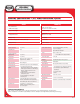

INDOOR DISPLAY
LEDARRAY
MNS
SERIES
6
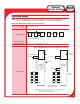
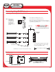
Networking one or more signs (shielded)
PWRL2
DISPLAY
SERIAL COM
L1
(RS 232/485)
(RS 232)
WH
BL
BR
YL
GN
OR
BK
RD
SHLD
+ RS485 (Black)
– RS485 (Red)
NOTE: When signs are
networked to the
CPU Module, all
the signs must be
the same model
when ALPHA
Messaging software
is used.
1-foot RS485 cable or
8-foot RS485 cable
To next
sign
Maximum = 4ØØØ feet (@ 96ØØ baud)
• Connect RED wire from RS485 cable to YL screw.
• Connect BLACK wire from RS485 cable to BK screw.
• ONLY connect SHIELD wire from RS485 cable to RD screw if the sign is a
Series 4ØØØ or Series 7ØØØ. For LEDarray, connect the two SHIELD wires
to each other, but not to the RD screw.
RS485 cable
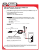
Connecting Using RS-485 Network
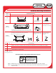
Enclosures
Use a twisted pair, 22awg with common shield.
Use modular adapter for network wiring.
Connect to sign with RJ-11 cable.
Mass Notification Signs
Connecting using RS-485 Network.
Modular Network
Adapter
FRONT VIEWSIDE VIEW
Backbox
Door
4"
1 7/8"
12"
12"
MNS-CONTROLLER
28.9"
4.5"
SIGN IS 2.1” DEEP
DISPLAY AREA IS 27”L x 2.1”H
POWER
MASS NOTIFICATION SYSTEM
MODEL G1212
SYSTEM CONTACT / SIGN NETWORK INTERFACE
See Figure 1
Page 4
LEDARRAY DISPLAY
Rev. 1
Install EOL Device on last sign in network (supplied with controller).