
User's Manual


BHS-i100 Installation and Programming Instructions
38
7 Supplemental information
7.1 System Specifications
Alarm output: Internal piezo siren
Transmission format: DTMF or pulse
Keypad enclosure: High-impact ABS plastic
Operating
temperature:
0-50 degrees C
Relative humidity: 0-95% non-condensing
Operating voltage 5 V Class 2 plug-in power supply
Residential system
weight:
1.5 pounds
Reporting format: SIA Level 1
Ringer equivalence: 0.1B
Standby power: 3.6 VDC, 1800 mAH NiMH battery
System test: Automatic and/or manually initiated
by the user/installer
UL compliance: UL 985, UL 1023, UL 1635, UL 1637
Zones: 59
7.2 Standby Battery Requirements
The table below identifies the battery backup times called for by
the regulatory requirements listed. For the duration of the
backup time, the system must function properly on DC power,
without false alarm.
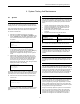
Requirement Backup time, hours
UL 985: Residential Fire 24
UL 1023: Residential Burglary 4
UL 1635: Mercantile 4
UL 1637: Home Health Care 24
7.3 Zone Types
The zones of the BHS-i100 can be programmed in one of the
following 14 ways:
• Unconfigured zone
• Entry / exit zone
• Exit Force Arm zone
• Instant zone
• Follower zone
• Day/ Night zone
• Medical zone
• Assault zone
• Silent assault zone
• Auxiliary zone
• Follow delay zone
• Fire zone
• Local zone
• Carbon Monoxide zone
Each zone type is described on the following pages.
7.3.1 Unconfigured Zone
This zone type is used for those zones for which no sensors are
installed (a disabled zone). No alarms can result from an
unconfigured zone.
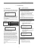
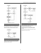
7.3.2 Entry / Exit Delay Zone
Zones that monitor the common points of entry and exit should
be programmed as entry/exit zones. The flowchart shows the
conditions under which a fault on an entry/exit delay results in
an alarm.
Entry / Exit Delay Zone
7.3.3 Exit Force Arm (Secondary Delay) Zone
Zones that monitor the building’s alternative points of entry and
exit should be programmed as secondary delay zones. An
example of this would be a garage door. This zone is not
enabled until it is restored at the close of the entry or exit delay.
The flowchart shows the conditions under which a fault on a
secondary delay zone results in an alarm.