
User Manual
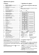
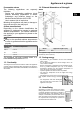
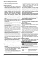
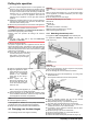
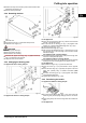
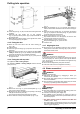
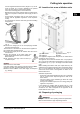
Table Of Contents
- 1 Appliance at a glance
- 2 General safety information
- 3 Controls and displays
- 4 Putting into operation
- 5 Control
- 5.1 Brightness of the temperature display
- 5.2 Child proofing
- 5.3 Door alarm
- 5.4 Temperature alarm
- 5.5 Freezing food
- 5.6 Thawing food
- 5.7 Setting the temperature
- 5.8 SuperFrost
- 5.9 Drawers
- 5.10 Shelves
- 5.11 VarioSpace
- 5.12 Information system
- 5.13 Drawer for herbs and berries
- 5.14 Cold storage accumulators
- 5.15 IceMaker*
- 6 Maintenance
- 7 Malfunctions
- 8 Decommissioning*
- 9 Disposing of the appliance
- l708619601_instructionmanual_SKBbs4210.pdf
- 1 Appliance at a glance
- 2 General safety information
- 3 Controls and displays
- 4 Putting into operation
- 5 Control
- 6 Maintenance
- 7 Malfunctions
- 8 Decommissioning
- 9 Disposing of the appliance
Use the supplied stainless steel hose (length 1.5 m). Do not
reuse old hoses. A 3 m hose is available as an optional
extra. This hose must be professionally installed.
In the hose connecting piece is a sieve with seal.
- Between the hose and the domestic water connection there
has to be a stopcock to interrupt the water supply in case of
need.
- All the fixtures and fittings used for water supply have to
comply with the applicable regulations of the respective
country.
- Do not damage or kink the water inlet pipe when installing
the appliance.
Fig. 13
u
Connect the straight part of the accompanying stainless
steel hose to the stopcock.
The solenoid is at the bottom on the back of the appliance. It
has a metric R3/4 connecting thread.
u
Connect the angled part of the stainless steel hose to the
solenoid valve.
u
Open the stopcock of the water supply and
check that the entire water system is leakproof.
Before initial use:
u
The domestic water pipe must be bled by a
competent expert.
NOTICE
Malfunction of the water intake!
If the water intake is shut off during operation but the IceMaker
remains in operation, the water intake pipe may ice up.
u
Switch off the IceMaker if the water supply is interrupted
(e.g. holiday).
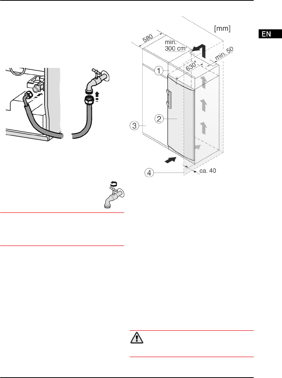
4.5 Insertion into a row of kitchen units
Fig. 14
(1) Stack cabinet (3) Kitchen cabinet
(2) Appliance (4) Wall
x
For appliances supplied with wall spacers, the measurement
increases by 35 mm (see 4.2) .
The appliance can be built into kitchen units. A top cupboard
Fig. 14 (2)
can be added above the appliance in order to bring
the appliance
Fig. 14 (1)
up to the height of the fitted kitchen
units.
When installing with kitchen units (max. depth 580 mm), the
appliance can be positioned directly next to the kitchen cabinet
Fig. 14 (3)
. The appliance will project by 34 mm
x
at the sides
and 50 mm
x
in the centre of the appliance in relation to the
kitchen cabinet front.
Ventilation requirements:
-
At the back of the stack cabinet there has to be a ventilation
duct of at least 50 mm depth throughout the width of the
stack cabinet.
-
The cross section of the ventilation gap below the ceiling
must be at least 300 cm
2
.
-
the larger the ventilation space, the more energy-saving the
appliance is in operation.
If the appliance is installed with the hinges next to a wall
Fig. 14 (4)
, the distance between appliance and wall has to be
at least 40 mm. This corresponds to the projection of the
handle when the door is open.
4.6 Disposing of packaging
WARNING
Danger of suffocation due to packing material and plastic film!
u
Do not allow children to play with packing material.
Putting into operation
* Depending on model and options 9