
User Manual
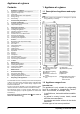
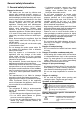
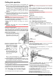
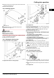
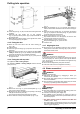
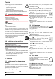
Table Of Contents
- 1 Appliance at a glance
- 2 General safety information
- 3 Controls and displays
- 4 Putting into operation
- 5 Control
- 5.1 Brightness of the temperature display
- 5.2 Child proofing
- 5.3 Door alarm
- 5.4 Temperature alarm
- 5.5 Freezing food
- 5.6 Thawing food
- 5.7 Setting the temperature
- 5.8 SuperFrost
- 5.9 Drawers
- 5.10 Shelves
- 5.11 VarioSpace
- 5.12 Information system
- 5.13 Drawer for herbs and berries
- 5.14 Cold storage accumulators
- 5.15 IceMaker*
- 6 Maintenance
- 7 Malfunctions
- 8 Decommissioning*
- 9 Disposing of the appliance
- l708619601_instructionmanual_SKBbs4210.pdf
- 1 Appliance at a glance
- 2 General safety information
- 3 Controls and displays
- 4 Putting into operation
- 5 Control
- 6 Maintenance
- 7 Malfunctions
- 8 Decommissioning
- 9 Disposing of the appliance
q
The more R 600a refrigerant there is in the appliance, the
larger the room in which the appliance is standing needs to
be. In rooms that are too small, a flammable mix of gas and
air may be created if there is a leak. According to the EN 378
standard, every 11 g of R 600a refrigerant requires at least
1 m
3
space in the room for the appliance. The amount of
refrigerant in your appliance is on the type plate inside the
appliance.
u
Detach the connecting cable from the rear of the appliance,
removing the cable holder at the same time because other-
wise there will be vibratory noise!
u
Remove the protective film from the outside of the appliance.
NOTICE
Risk of damage from stainless steel care products!
The stainless steel doors and stainless steel side walls are
finished with a high-quality surface coating.
Stainless steel care products will damage the surfaces.
u
Use only a soft, clean cloth to wipe the coated door
surfaces and side walls.
u
Remove all transit supports.
The spacers supplied with some appliances must be used to
achieve the stated energy consumption. These will extend the
depth of the appliance by approx. 35 mm. The appliance is fully
functional if the spacers are not used, but does have a slightly
higher energy consumption.
u
In the case of an appliance with
enclosed wall spacers, mount the
wall spacers on the back of the
appliance at the top left and right.
u
Dispose of packaging material (see 4.6) .
u
Align the appliance so that it
stands firmly and on a level by
applying the accompanying
spanner to the adjustable-
height feet (A) and using a
spirit level.
u
Then support the door:
Extend the adjustable foot at
the turn hinge (B) until it rests
on the floor and then make a
further 90° turn.
When a Side-by-Side appliance (S…) is fitted together with
a second appliance (as a SBS combination):
u
Proceed according to the Side-by-Side combined fridge-
freezer installation instructions. (Accessories bag of the SBS
freezer/appliance with freezer compartment)
Note
u
Clean the appliance (see 6.2) .
If the appliance is installed in a very damp environment,
condensate may form on the outside of the appliance.
u
Always see to good ventilation at the installation site.
4.3 Changing over the door hinges
You can change over the door hinges if necessary.
NOTICE
Risk of damage to side-by-side appliances due to condensa-
tion!
When a side-by-side appliance (S…) is fitted together with a
second appliance (as a SBS combination), the door hinges
must remain as delivered.
u
Do not change over the door hinges.
Ensure that the following tools are to hand:
q
Torx® 25
q
Torx® 15
q
Screwdriver
q
Cordless screwdriver, if necessary
q
Second person for fitting work, if needed
q
Accompanying Allen key size 2
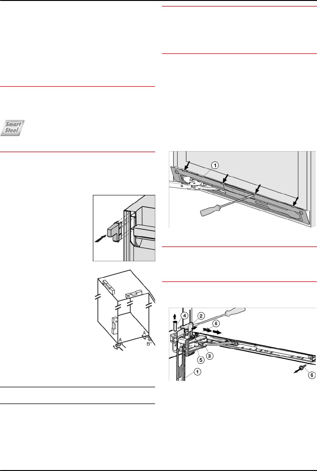
4.3.1 Detaching the soft stop unit.*
For appliances with a closing damper, start with this point.
For appliances without a closing damper, start with this
point: (see 4.3.2) .
Fig. 4
u
Open the door.
NOTICE
Risk of damage!
If the door seal is damaged, the door may fail to close properly
and the cooling will be inadequate.
u
Do not damage the door seal with the screwdriver!
u
Disengage and remove the faceplate
Fig. 4 (1)
using a flat-
blade screwdriver.
w
The faceplate is attached over the soft stop bracket.
Fig. 5
u
Slide the faceplate forwards over the soft stop bracket
Fig. 5 (5)
in the direction of the appliance.
u
Snap the safety lock
Fig. 5 (3)
into the oblong hole.
w
The safety lock prevents the hinge from snap-closing.
u
Using a screwdriver, lift off the cover
Fig. 5 (2)
from the
outside and remove it in an outward direction.
u
If necessary, tip the appliance backwards with the assis-
tance of a second person.
u
Press the pin
Fig. 5 (4)
out from underneath.
u
Press the soft stop bracket
Fig. 5 (5)
towards the door.
u
Remove the faceplate
Fig. 5 (1)
.
u
Unscrew the entire soft stop unit (2x Torx® 15)
Fig. 5 (6)
.
Putting into operation
6 * Depending on model and options