
User Manual
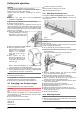
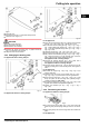
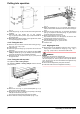
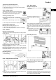
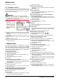
Table Of Contents
- 1 Appliance at a glance
- 2 General safety information
- 3 Controls and displays
- 4 Putting into operation
- 5 Control
- 5.1 Brightness of the temperature display
- 5.2 Child proofing
- 5.3 Door alarm
- 5.4 Temperature alarm
- 5.5 Freezing food
- 5.6 Thawing food
- 5.7 Setting the temperature
- 5.8 SuperFrost
- 5.9 Drawers
- 5.10 Shelves
- 5.11 VarioSpace
- 5.12 Information system
- 5.13 Drawer for herbs and berries
- 5.14 Cold storage accumulators
- 5.15 IceMaker*
- 6 Maintenance
- 7 Malfunctions
- 8 Decommissioning*
- 9 Disposing of the appliance
- l708619601_instructionmanual_SKBbs4210.pdf
- 1 Appliance at a glance
- 2 General safety information
- 3 Controls and displays
- 4 Putting into operation
- 5 Control
- 6 Maintenance
- 7 Malfunctions
- 8 Decommissioning
- 9 Disposing of the appliance

4.4 Insertion into a row of kitchen units
Fig. 13
(1) Stack cabinet (3) Kitchen cabinet
(2) Appliance (4) Wall
x
For appliances supplied with wall spacers, the measurement
increases by 35 mm (see 4.2) .
The appliance can be built into kitchen units. A top cupboard
Fig. 13 (2)
can be added above the appliance in order to bring
the appliance
Fig. 13 (1)
up to the height of the fitted kitchen
units.
When installing with kitchen units (max. depth 580 mm), the
appliance can be positioned directly next to the kitchen cabinet
Fig. 13 (3)
. The appliance will project by 34 mm
x
at the sides
and 50 mm
x
in the centre of the appliance in relation to the
kitchen cabinet front.
Ventilation requirements:
-
At the back of the stack cabinet there has to be a ventilation
duct of at least 50 mm depth throughout the width of the
stack cabinet.
-
The cross section of the ventilation gap below the ceiling
must be at least 300 cm
2
.
-
the larger the ventilation space, the more energy-saving the
appliance is in operation.
If the appliance is installed with the hinges next to a wall
Fig. 13 (4)
, the distance between appliance and wall has to be
at least 40 mm. This corresponds to the projection of the
handle when the door is open.
4.5 Disposing of packaging
WARNING
Danger of suffocation due to packing material and plastic film!
u
Do not allow children to play with packing material.
The packaging is made of recyclable materials:
-
corrugated board/cardboard
-
expanded polystyrene parts
-
polythene bags and sheets
-
polypropylene straps
-
nailed wooden frame with polyethylene panel*
u
Take the packaging material to an official collecting point.
4.6 Connecting the appliance
NOTICE
Failure to connect properly
Damage to the electronics.
u
Do not use a standalone inverter.
u
Do not use an energy saving plug.
WARNING
Failure to connect properly
Fire.
u
Do not use an extension cable.
u
Do not use distributor blocks.
The type of current (alternating current) and voltage at the
installation site have to conform with the data on the type plate
(see Appliance at a glance).
The socket must be properly earthed and fused. The tripping
current for the fuse must be between 10 A and 16 A.
The socket must be easily accessible so that the appliance can
be quickly disconnected from the supply in an emergency. It
must be outside the area of the rear of the appliance.
u
Check the electrical connection.
u
Plug in the power plug.
4.7 Switching on the appliance
u
Press On/Off button
Fig. 3 (6)
.
w
The temperature display indicates the current temperature.
w
The interior light is on when the door is open.
w
If “DEMO” is displayed, demo mode is activated. Please
contact the after sales service.
5 Control
5.1 Brightness of the temperature
display
You can adjust the brightness of the temperature display to the
light conditions of the room in which the appliance is installed.
5.1.1 Adjusting the brightness
The brightness is adjustable between h0 (no illumination) and
h5 (maximum luminosity).
u
To activate the setting mode: press SuperCool button
Fig. 3 (7)
for about 5s.
w
The display indicates c.
w
The menu symbol
Fig. 3 (4)
shines.
u
Using the Up setting button
Fig. 3 (2)
and Down setting
button
Fig. 3 (3)
, select h.
u
To confirm: briefly press the SuperCool button
Fig. 3 (7)
.
Control
* Depending on model and options 9