
User Manual


LH 80 C Litronic Machine for Industrial Applications 5
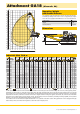
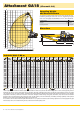
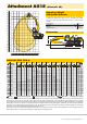
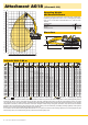
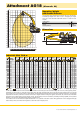
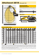
Attachment GA18 (Kinematic 2A)
3450
8250
15150
H0193
Dimensions
ft
m
70
22
20
18
16
14
12
10
8
6
4
2
0
-2
-4
-6
-8
-10
65
60
55
50
45
40
35
30
25
20
15
10
5
0
-5
-10
-15
-20
-25
-30
02468101214161820
65 60 55 50 45 40 35 30 25 20 15 10 5 0
ft m
H0012
Operating Weight
and Ground Pressure
The operating weight includes basic machine with rigid cab elevation,
industrial-type straight mono boom 10.50 m, industrial-type angled
stick 7.80 m and grapple model GMM 80-5/1.70 m
3
semi-closed tines.
Undercarriage EW
Pad width mm 600
Weight kg 68,400
Ground pressure on request
Industrial Stick 7.80 m
m
Under-
carriage
4.5 m 6.0 m 7.5 m 9.0 m 10.5 m 12.0 m 13.5 m 15.0 m 16.5 m 18.0 m 19.5 m 21.0 m
m
22.5
EW
21.0
EW
19.5
EW
14.5* 14.5*
5.7
18.0
EW
14.2* 14.2* 11.4* 11.4* 11.2* 11.2*
9.1
16.5
EW
15.5* 15.5* 14.0* 14.0* 11.7* 11.7* 9.8* 9.8*
11.3
15.0
EW
13.9* 13.9* 12.4* 12.4* 11.3* 11.3* 9.0* 9.0*
12.9
13.5
EW
13.8* 13.8* 12.3* 12.3* 11.2* 11.2* 9.5 10.3* 8.5* 8.5*
14.2
12.0
EW
13.8* 13.8* 12.3* 12.3* 11.1* 11.1* 9.6 10.2* 7.7 9.1* 7.4 8.2*
15.3
10.5
EW
13.9* 13.9* 12.4* 12.4* 11.2* 11.2* 9.6 10.2* 7.8 9.4* 6.7 8.0*
16.1
9.0
EW
16.5* 16.5* 14.3* 14.3* 12.6* 12.6* 11.3* 11.3* 9.4 10.3* 7.7 9.4* 6.3 8.2 6.1 7.9*
16.7
7.5
EW
18.2* 18.2* 17.2* 17.2* 14.7* 14.7* 12.9* 12.9* 11.3 11.5* 9.2 10.4* 7.6 9.5* 6.3 8.2 5.7 7.5
17.2
6.0
EW
19.9* 19.9* 22.3* 22.3* 18.1* 18.1* 15.3* 15.3* 13.3* 13.3* 10.9 11.7* 8.9 10.5* 7.4 9.5 6.2 8.1 5.4 7.1
17.6
4.5
EW
32.6* 32.6* 24.0* 24.0* 19.1* 19.1* 15.9* 15.9* 12.9 13.7* 10.4 12.0* 8.6 10.7* 7.2 9.3 6.0 7.9 5.2 6.9
17.8
3.0
EW
5.3* 5.3* 25.5* 25.5* 20.0* 20.0* 15.3 16.4* 12.2 14.0* 9.9 12.2* 8.2 10.7 6.9 9.1 5.9 7.8 5.1 6.8
17.9
1.5
EW
3.1* 3.1* 12.0* 12.0* 18.7 20.5* 14.4 16.8* 11.5 14.2* 9.5 12.3* 7.9 10.4 6.7 8.8 5.7 7.6 5.1 6.7
17.9
0
EW
3.6* 3.6* 9.2* 9.2* 17.6 20.5* 13.6 16.8* 11.0 14.2* 9.1 12.0 7.6 10.1 6.5 8.7 5.6 7.5 5.1 6.3*
17.7
– 1.5
EW
4.9* 4.9* 9.2* 9.2* 16.9 18.4* 13.1 16.3* 10.6 13.8* 8.8 11.7 7.4 9.9 6.4 8.5 5.6 7.0* 5.2 5.8*
17.3
– 3.0
EW
10.0* 10.0* 16.6 17.4* 12.8 15.1* 10.3 12.9* 8.6 11.0* 7.3 9.3* 6.3 7.7* 5.8 6.3*
16.1
– 4.5
EW
12.7 13.0* 10.2 11.2* 8.5 9.5* 7.3 7.9* 7.1 7.6*
13.7
– 6.0
EW
Height Can be slewed through 360° In longitudinal position of undercarriage Max. reach * Limited by hydr. capacity
The lift capacities on the stick end without attachment are stated in metric tons (t) and can be slewed through 360° on a firm, level supporting surface.
Capacities are valid for 600 mm wide triple grouser pads (resp. flat pads). Indicated loads comply with the ISO 10567 standard and do not exceed
75 % of tipping or87 % of hydraulic capacity. The lift capacity values indicated are attained at the corresponding operating temperature. This operating
temperature is ensured by continuous movement of the boom. Weights of fitted working tools (grabs, load hooks, etc.) and load accommodation
equipment are to be deducted from the lift capacity values. The lift capacity of the unit is limited by its stability, the lifting capability of the hydraulic
elements, or the maximum permissible lifting capacity of the load hook.
In accordance with the harmonised European Standard EN 474-5, hydraulic excavators used for lifting operations must be equipped with pipe
fracturesafety valves, an overload warning device, a load hook and a lift capacity chart.