
Assembly and installation instructions

11
I
ce
m
aker
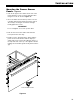
Figure 19
Figure 17
Figure 20
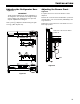
9. Open the shut-off valve for the water supply and
check the entire water system for leaks.
Connection to the Water Supply
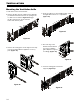
1. Move the appliance towards the final position and
leave enough space to work behind.
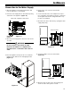
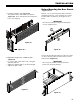
2. Insert the water supply line into its intended opening
at the back of the appliance (Figure 17).
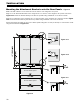
4. Move the appliance slowly into the recess until the
appliance back slides into the anti tipping bracket
(Figure 18).
3. Move the power supply line to the area of the electri-
cal outlet.
WARNING!
Donotconnecttotheelectricaloutlet
before the installation is completed and
the water line is connected to the solenoid
valve.
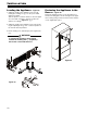
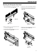
5. Remove the cover from the solenoid valve
(Figure 19).
6. Connect the water line to the adapter in the respec-
tive configuration, depending on the type of water line
used. Figure 19 shows the configuration with a cop-
per line as an example.
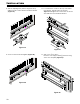
7. Bleed the air from the water line by opening the water
supply temporarily.
Back view of appliance bottom left
Figure 18
8. Screw the adapter onto the solenoid valve
(Figure 20).
Solenoid valve