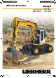
Wheeled Excavator A 900 C Operating Weight: 17,400 - 19,600 kg Engine Output: 95 kW / 129 HP Bucket Capacity: 0.32 - 0.95 m³ A A 900 900 C_Litronic_EN.indd C_Litronic.indd 1 1 15.04.2010 15.04.
A 900 C Operating Weight: 17,400 - 19,600 kg Engine Output: 95 kW / 129 HP Bucket Capacity: 0.32 - 0.95 m³ 2 A 900 C Litronic A A 900 900 C_Litronic_EN.indd C_Litronic.indd 2 2 15.04.2010 15.04.
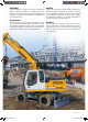
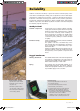
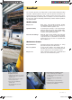
Reliability Comfort Liebherr hydraulic excavators have been designed and built to withstand the toughest of conditions at the building site. Their rugged design, high-tensile materials and individual components ensure maximum availability and long life-expectancy. Largely dimensioned and ergonomically designed, the Liebherr excavator cab features an operator’s seat which can be individually adjusted, as well as clearly arranged control instruments and ideal all-round view.
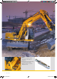
Features • High-tensile steel plates in highstress areas for the toughest of applications • Well-thought-out and secure bearings for attachments and cylinders • Maximum resistance, even when lifting heavy loads 4 A 900 C Litronic A A 900 900 C_Litronic_EN.indd C_Litronic.indd 4 4 15.04.2010 15.04.
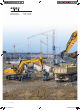
Reliability Liebherr construction machinery is proven all over the world every day on the most diverse of building sites. Many years of experience as the world’s largest manufacturer of rubber-tyre excavators, continuous development and the introduction of the latest technology are evident in every machine, guaranteeing absolute safety during applications. With its rugged design, and featuring Liebherr components, the Liebherr hydraulic excavators have been designed for extremely long life-expectancy.
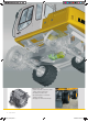
Liebherr diesel engine • Long life-expectancy, expansive cylinder capacity and increased weight • According to level IIIA / Tier 3 • Specially designed for construction machinery operation • Oil supply even with extreme tilt angle 6 A 900 C Litronic A A 900 900 C_Litronic_EN.indd C_Litronic.indd 6 6 15.04.2010 15.04.
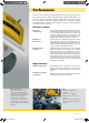
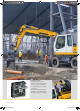
Performance Liebherr wheel excavators have been designed for maximum productivity. Perfectly harmonized, the Liebherr-developed and Liebherr-manufactured components including diesel engine, hydraulic pump and motor, as well as swing gear and cylinders, guarantee maximum performance. Tremendous digging and breakout forces, extensive lifting capacities and quick working and travel movements are thus resulted.
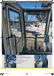
Large-sized cab • Adjustable steering column • Operator’s seat, adjustable in height and can also be adapted to the individual weight of the operator. • Consoles with or without possibility of horizontal adjustment. • Large roof window • Sun blinds 8 A 900 C Litronic A A 900 900 C_Litronic_EN.indd C_Litronic.indd 8 8 15.04.2010 15.04.
Comfort The excavator operator is provided with an ergonomically-arranged working area within Liebherr hydraulic excavator cabs. All switches and functions are logically laid out, and operator’s seat, steering column and consoles can be adjusted individually. Conditioning and concentration can thus be maintained throughout the entire working day, guaranteeing constant, maximum productivity of the operator.
Hydrostatic fan drive • Accelerated warm-up period • Guaranteed constant oil quality as a result of constant oil temperature • Increased life-expectancy of drive components • The fan only runs at the output required, thus conserving fuel and reducing the noise level considerably 10 A 900 C Litronic A A 900 900 C_Litronic_EN.indd C_Litronic.indd 10 10 15.04.2010 15.04.
Economy Liebherr offer a wide range of models, guaranteeing optimum suitability for every application. Easy access to components, as well as the proven service offer allows maintenance tasks to be performed in the shortest of times, thus reducing operating costs considerably. Low operating costs Solid Liebherr Engine Maximum power of the engine is generated even when running at minimum speed.
Technical Data Engine Swing Drive Rating per ISO 9249 ��������� 95 kW (129 HP) at 1,800 RPM Model������������������������������ Liebherr D 934 S according to level IIIA / Tier 3 Type ������������������������������� 4 cylinder in-line Bore/Stroke���������������� 122/136 mm Displacement ������������� 6.
Dimensions E D A C W H K Q M T1 L B B1 U1 V X J3 I3 I2 J2 T2 U2 T3 B T1 U3 B2 B B3 B1 A B B1) B1 B2 B21) B3 C D E H I2 I3 J2 J3 K L M Q T1 T2 T3 U1 U2 U3 1) = EW-Undercarriage E = Tail radius Tires 10.00-20 mm 2,550 2,550 2,750 3,690 2,550 2,750 2,550 3,160 2,260 2,330 2,465 425 380 605 585 1,235 2,540 1,100 360 1,050 1,225 1,155 4,390 4,575 4,740 Stick Hydr. Adjustable Gooseneck Boom Boom 3.60 m 5.00 m stabil. 2 pt. blade 4 pt. stabil. 2 pt. blade 4 pt.
Backhoe Attachment with Hydr. Adjustable Boom 3.60 m ft m 11 35 Digging Envelope with Quick Change Adapter 1 2 3 2.25 2.45 2.65 10 30 Stick length m Max. digging depth Max. reach at ground level Max. dumping height Max. teeth height Min. attachment radius m 5.65 m 9.10 m 7.20 m 10.30 m 2.85 9 8 25 7 20 6 5 15 Digging Forces without Quick Change Adapter 4 10 3 Max. digging force (ISO 6015) 2 Max. breakout force (ISO 6015) 5 1 0 -1 -2 3 81.0 8.3 98.4 10.0 76.0 7.7 98.
Lift Capacities with Hydr. Adjustable Boom 3.60 m Stick 2.25 m m 3.0 m Stick 2.45 m 4.5 m 6.0 m 7.5 m Undercarriage 9.0 7.5 6.0 4.5 3.0 1.5 0 – 1.5 – 3.0 – 4.5 Stabilizers raised Stabilizer blade down 2 pt. outriggers down Blade + 2 pt. down 4 pt. outriggers down Stabilizers raised Stabilizer blade down 2 pt. outriggers down Blade + 2 pt. down 4 pt.
Lift Capacities with Hydr. Adjustable Boom 3.60 m EW-Undercarriage Stick 2.25 m m Stick 2.45 m 3.0 m 4.5 m 6.0 m 7.5 m Undercarriage m 3.36 5.41 Stabilizers raised Stabilizer blade down 2 pt. outriggers down 3.9* 3.9* 3.9* 3.9* 3.9* 3.9* 2.1* 2.1* 2.1* 2.1* 2.1* 2.1* 5.70 2.1* 2.1* 2.1* 6.73 Stabilizers raised Stabilizer blade down 2 pt. outriggers down 4.3* 4.3* 4.3* 4.3* 4.3* 4.3* 3.2 3.4 3.8* 3.8* 3.8* 3.
Backhoe Attachment with Gooseneck Boom 5.00 m ft m 10 30 9 25 Digging Envelope with Quick Change Adapter 15 6 5 4 10 3 Stick length m 2.25 2.45 2.65 Max. digging depth Max. reach at ground level Max. dumping height Max. teeth height Min. attachment radius m m m m m 5.50 8.80 6.15 9.00 3.30 5.70 9.00 6.25 9.10 3.05 5.90 9.20 6.40 9.25 3.05 1 2 3 kN 81.0 t 8.3 kN 98.4 t 10.0 76.0 7.7 98.4 10.0 71.6 7.3 98.4 10.0 Digging Forces without Quick Change Adapter 3 2 Max.
Lift Capacities with Gooseneck Boom 5.00 m Stick 2.25 m m 3.0 m Stick 2.45 m 4.5 m 6.0 m 7.5 m Undercarriage 9.0 7.5 6.0 4.5 3.0 1.5 0 – 1.5 – 3.0 – 4.5 Stabilizers raised Stabilizer blade down 2 pt. outriggers down Blade + 2 pt. down 4 pt. outriggers down Stabilizers raised Stabilizer blade down 2 pt. outriggers down Blade + 2 pt. down 4 pt.
Lift Capacities with Gooseneck Boom 5.00 m EW-Undercarriage Stick 2.25 m m Stick 2.45 m 3.0 m 4.5 m 6.0 m 7.5 m Undercarriage m Stabilizers raised Stabilizer blade down 2 pt. outriggers down Stabilizers raised Stabilizer blade down 2 pt. outriggers down 2.3* 2.3* 2.3* 2.3* 2.3* 2.3* Stabilizers raised Stabilizer blade down 2 pt. outriggers down 3.0 3.0* 3.0* 3.0* 3.0* 3.0* 2.0* 2.0* 2.
Backhoe Attachment with Adjustable Up/Down Plus Offset Boom 3.60 m ft m 11 35 Digging Envelope with Quick Change Adapter 10 30 25 m 5.65 m 9.15 m 7.20 m 10.30 m 2.85 1 stick 2.25 m 2 stick 2.45 m 3 stick 2.65 m at max. attachment offset with vertical ditch walls 2 1 0 1 -2 without Quick Change Adapter 2 3 Max. digging force (ISO 6015) -3 -10 Max. breakout force (ISO 6015) -4 -15 4 -5 5 -6 10 9 8 25 6 20 5 4 15 5 6 81.0 8.3 98.4 10.0 76.0 7.7 98.4 10.0 71.6 7.3 98.
Lift Capacities with Adjustable Up/Down Plus Offset Boom 3.60 m Stick 2.25 m m 3.0 m Stick 2.45 m 4.5 m 6.0 m 7.5 m Undercarriage 9.0 7.5 6.0 4.5 3.0 1.5 0 – 1.5 – 3.0 – 4.5 Stabilizers raised Stabilizer blade down 2 pt. outriggers down Blade + 2 pt. down 4 pt. outriggers down Stabilizers raised Stabilizer blade down 2 pt.
Lift Capacities with Adjustable Up/Down Plus Offset Boom 3.60 m EW-Undercarriage Stick 2.25 m m Stick 2.45 m 3.0 m 4.5 m 6.0 m 7.5 m Undercarriage m 3.38 5.42 Stabilizers raised Stabilizer blade down 2 pt. outriggers down 3.9* 3.9* 3.9* 3.9* 3.9* 3.9* 2.0* 2.0* 2.0* 2.0* 2.0* 2.0* 5.72 2.0* 2.0* 2.0* 6.74 Stabilizers raised Stabilizer blade down 2 pt. outriggers down 4.3* 4.3* 4.3* 4.3* 4.3* 4.3* 3.2 3.4 3.8* 3.
Backhoe Attachment with Adjustable Offset Boom 4.90 m ft m 10 30 9 25 Digging Envelope with Quick Change Adapter 8 7 20 15 6 5 4 10 5 3 2 1 0 0 -1 -5 -10 1 -2 6 Stick length m 2.25 2.45 2.65 Max. digging depth Max. reach at ground level Max. dumping height Max. teeth height Min. attachment radius m m m m m 5.40 8.85 6.30 9.15 3.20 5.60 9.05 6.45 9.30 3.25 1 stick 2.25 m 2 stick 2.45 m 3 stick 2.65 m at max. attachment offset with vertical ditch walls 4 stick 2.
Lift Capacities with Adjustable Offset Boom 4.90 m Stick 2.25 m m 3.0 m Stick 2.45 m 4.5 m 6.0 m 7.5 m Undercarriage 9.0 7.5 6.0 4.5 3.0 1.5 0 – 1.5 – 3.0 – 4.5 Stabilizers raised Stabilizer blade down 2 pt. outriggers down Blade + 2 pt. down 4 pt. outriggers down Stabilizers raised Stabilizer blade down 2 pt. outriggers down Blade + 2 pt.
Lift Capacities with Adjustable Offset Boom 4.90 m EW-Undercarriage Stick 2.25 m m Stick 2.45 m 3.0 m 4.5 m 6.0 m 7.5 m Undercarriage m Stabilizers raised Stabilizer blade down 2 pt. outriggers down Stabilizers raised Stabilizer blade down 2 pt. outriggers down 2.2* 2.2* 2.2* 2.2* 2.2* 2.2* Stabilizers raised Stabilizer blade down 2 pt. outriggers down 2.3* 2.3* 2.3* 2.3* 2.3* 2.3* 1.9* 1.9* 1.
Clamshell Attachment with Hydr. Adjustable Boom 3.60 m ft m Digging Envelope 10 30 with Quick Change Adapter 9 8 25 7 20 6 5 15 4 10 3 2 5 -1 -5 -2 -5 -6 1 -7 -25 -8 10 9 30 8 7 25 6 20 5 4 15 Clamshell Model 8 B 2 2.45 2.65 Max. digging depth Max. reach at ground level Max. dumping height m 6.80 m 8.90 m 6.65 7.00 9.10 6.80 7.20 9.30 7.00 Clamshell Model 8 B Max. tooth force Max. torque of hydr. swivel 52 kN (5.3 t) 1.
Clamshell Attachment with Hydr. Adjustable Boom 3.60 m ft m Digging Envelope 10 30 25 with Quick Change Adapter 9 8 7 20 15 6 5 4 10 5 3 2 -1 -2 -20 -3 -5 -6 -8 1 10 9 30 8 7 25 6 20 5 4 15 Clamshell Model 10 B 2 2.45 2.65 Max. digging depth Max. reach at ground level Max. dumping height m 6.80 m 8.90 m 6.65 7.00 9.10 6.80 7.20 9.30 7.00 Clamshell Model 10 B Max. tooth force Max. torque of hydr. swivel 73 kN (7.4 t) 1.
Clamshell Attachment with Gooseneck Boom 5.00 m ft m 30 9 with Quick Change Adapter 8 7 25 20 Digging Envelope 6 1 2 3 Stick length m 2.25 2.45 2.65 Max. digging depth Max. reach at ground level Max. dumping height m 6.70 m 8.60 m 5.45 6.90 8.80 5.55 7.10 9.00 5.70 5 15 4 10 3 Clamshell Model 8 B Max. tooth force Max. torque of hydr. swivel 52 kN (5.3 t) 1.
Clamshell Attachment with Gooseneck Boom 5.00 m ft m 30 9 with Quick Change Adapter 8 7 25 20 15 Digging Envelope 6 2 3 Stick length m 2.25 2.45 2.65 Max. digging depth Max. reach at ground level Max. dumping height m 6.70 m 8.60 m 5.45 6.90 8.80 5.55 7.10 9.00 5.70 5 4 10 1 3 Clamshell Model 10 B Max. tooth force Max. torque of hydr. swivel 73 kN (7.4 t) 1.
Attachments Ditchcleaning Buckets/Tilting Buckets Ditchcleaning Buckets Machine stability per ISO 10567* (75 % of tipping capacity) 2 point outriggers down Stabilizer blade + 2 pt. outr.
Equipment Undercarriage 2-circuit brake system Support individually controllable Tires Mitas EM 22 Wide gauge 2.
NTB_RS_A4_D.qxd 26.03.2007 8:53 Uhr Seite 1 The Liebherr Group of Companies Wide product range State-of-the-art technology The Liebherr Group is one of the largest construction equipment manufacturers in the world. Liebherr’s highvalue products and services enjoy a high reputation in many other fields, too. The wide range includes domes tic appliances, aerospace and transportation systems, machine tools and maritime cranes.