POWER AVAILABILITY PowerSure PSI™ USER MANUAL 1000 - 3000VA 230V Version française, : reportez-vous au CD du guide d'utilisateur Liebert. Para español, consulte el CD del Manual del Usuario de Liebert. Die deutsche Fassung finden Sie auf der CD des Liebert-Benutzerhandbuchs. Per l'Italiano, consultare il CD contenente il Manuale dell'utente Liebert.
TABLE OF CONTENTS IMPORTANT SAFETY INSTRUCTIONS . . . . . . . . . . . . . . . . . . . . . . . . . . . . . . . . . . . . . . . . . . . . . . . .1 1.0 GLOSSARY OF SYMBOLS. . . . . . . . . . . . . . . . . . . . . . . . . . . . . . . . . . . . . . . . . . . . . . . . . . .3 2.0 INTRODUCTION . . . . . . . . . . . . . . . . . . . . . . . . . . . . . . . . . . . . . . . . . . . . . . . . . . . . . . . . . .4 3.0 MAJOR COMPONENTS . . . . . . . . . . . . . . . . . . . . . . . . . . . . . . . . . . . . . . . . .
9.0 VOLTAGE PROGRAMMING PROCEDURE . . . . . . . . . . . . . . . . . . . . . . . . . . . . . . . . . . . . . . . 21 10.0 MAINTENANCE . . . . . . . . . . . . . . . . . . . . . . . . . . . . . . . . . . . . . . . . . . . . . . . . . . . . . . . . . 22 10.1 10.2 10.3 Cleaning the UPS . . . . . . . . . . . . . . . . . . . . . . . . . . . . . . . . . . . . . . . . . . . . . . . . . . . . . . . . . . . 22 Maintaining Batteries . . . . . . . . . . . . . . . . . . . . . . . . . . . . . . . . . . . . . . . . . .
IMPORTANT SAFETY INSTRUCTIONS SAVE THESE INSTRUCTIONS This manual contains important safety instructions that should be followed during the installation and maintenance of the UPS and batteries. Please read this manual thoroughly before attempting to install or operate this UPS.
CONDITIONS OF USE: The mains supply socket must be within 2m (6.5 ft.) of the UPS and be easily accessible. Your UPS provides conditioned power to connected equipment. This product is designed for Commercial use only. It is not intended for use with life support and other designated “critical” devices. Maximum load must not exceed that shown on the UPS rating label. If uncertain, consult your local dealer, Liebert representative or the Liebert Worldwide Support Group.
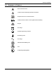
Glossary of Symbols. 1.0 GLOSSARY OF SYMBOLS.
Introduction 2.0 INTRODUCTION Congratulations on your choice of the Liebert PowerSure™ PSI Uninterruptible Power Supply (UPS). It provides conditioned power to microcomputers and other sensitive electronic equipment. Upon generation, AC power is clean and stable. However, during transmission it may be subject to voltage sags, spikes, or complete power failure which may interrupt computer operations, cause data loss, or even damage equipment. The PowerSure PSI protects equipment from these disturbances.
Introduction Figure 2 REPO 1000 and 1440VA PSI—rear view Intellislot Port Output Data Line Connectors Receptacles Circuit Breaker INPUT BREAKER PUSH TO RESET OUT REPO IN LOAD 1 BATTERY CONNECTOR 1440VA/DC 48V/30A 1000VA/DC 48V/20A PHONE / FAX / MODEM / NETWORK PROTECTION RS-232 1 2 3 4 + INPUT LOAD 2 - INTELLISLOT External Battery Cabinet Connector AC Input USB Port RS232 (DB-9) Port Figure 3 REPO 2200 and 3000VA PSI—rear view Intellislot Port Input Circuit Breaker Data Line Connecto
Major Components 3.0 MAJOR COMPONENTS Figure 4 Line diagram of PowerSure PSI 1000VA & 1440VA Input EMI/RFI Filter Relay AVR Transformer Charger Battery Inverter Output G G Figure 5 Line diagram of PowerSure PSI 2200VA & 3000VA Input EMI/RFI Filter Relay AVR Transformer Charger Battery DC-to-DC Converter Output Bi-Directional Converter G 3.
Major Components 3.3 Automatic Voltage Regulator The Automatic Voltage Regulator (AVR) protects connected equipment from power spikes, sags and other abnormalities by raising (boosting) or lowering (bucking) the output voltage as needed. This keeps the UPS output voltage within the connected equipment’s tolerance and accommodates wide mains voltage fluctuations without utilizing the batteries. 3.
What’s Included 4.0 WHAT’S INCLUDED The PowerSure PSI is shipped with the following items: • • • • • • • • • • • • • PowerSure PSI user manual MultiLink software CD MultiLink serial cable, 3m (10 ft) USB cable, 1.8m (6 ft) RJ-11 cord, 2.1m (7 ft) Rack mount handles Support base Fixed rails Mounting hardware (screws/washers) Front bezel Vertical display overlay Two (2) 10A output power cords, 2.0m (6.6 ft.
Installation 5.0 INSTALLATION 5.1 Preparation 1. Visually inspect the UPS for freight damage. Report damage to the carrier and your local dealer or Liebert representative. ! CAUTION The UPS is heavy (see Table 4 - Battery cabinet specifications). Take proper precautions when lifting or moving it. 2. Decide where to place the PowerSure PSI. Install the UPS indoors in a controlled environment where it cannot be accidentally turned Off.
Installation 5.3 Rack-Mount UPS Conversion and Installation NOTE When rack mounted, the UPS must be supported by a shelf, slide rails, brackets or fixed rails on each side. The rack mount handles WILL NOT support the weight of the UPS. They are used to move the UPS into and out of the rack. 1. For fixed rail installations, install the rack mount handles using four (4) M4x6 screws (see Figure 7).
Installation 4. Attach the two (2) fixed rails to the racks mounting rails. The fixed rail assemblies fit on the inside of the rack mounting rails. 5. Insert two (2) M5 flat head screws loosely (finger-tight) into the top and bottom holes on the front of the fixed rail assembly (see Figure 9). 6. Extend fixed rail by sliding inner member backward until it touches the rear rack mounting rail. 7. Insert two (2) M5 screws loosely (finger-tight) into top and bottom holes on the rear of the fixed rail assembly.
Installation 15. Connect Phone/Fax/DSL/Network/Modem devices to data line connectors. RJ11/RJ45 connection INPUT BREAKER PUSH TO RESET OUT REPO IN LOAD 1 BATTERY CONNECTOR 1440VA/DC 48V/30A 1000VA/DC 48V/20A PHONE / FAX / MODEM / NETWORK PROTECTION RS-232 1 2 3 4 + INPUT LOAD 2 - INTELLISLOT 16. Communication options (see 8.0 - Communications for details): Option 1 - Serial Communications Serial communications provides parametric data, for example, input voltage and battery voltage. a.
Installation Figure 10 REPO switch connections REPO Connector REPO Switch as shipped 1 2 3 REPO connections for normally open switch system 4 1 2 3 REPO connections for normally closed switch system (fail-safe) 4 1 2 3 4 Key to REPO switch connections 1. 24 VDC, 2. Sense 3. Sense 4. Ground External Battery Cabinet Installation Optional Liebert external battery cabinets may be connected to the UPS to provide additional battery run time.
Controls and Indicators 6.0 CONTROLS AND INDICATORS All indicators illuminated for illustrative purposes only. 6.1 ON/Alarm Silence/Battery Test Button This button controls output power to connected load(s) and has three functions: • On • Alarm Silence • Battery Test ON—When the UPS is Off, pressing the ON/Alarm Silence/Battery Test button for more than one (1) second will start the UPS, and an audible alarm sounds briefly. The UPS is capable of starting on battery (battery start).
Controls and Indicators 6.3 Voltage Programming Button The PowerSure PSI contains a Voltage Programming button that allows the operator to select the nominal mains voltage. This setting changes the mains transfer points (low and high) of the UPS and the nominal output voltage when operating in Battery mode. The operator can select between 220, 230 and 240VAC output. The factory-default setting is 230VAC.
Controls and Indicators 6.9 Over Temp Indicator—Amber The Over Temp Indicator flashes when the UPS detects an over temperature condition. This indicator illuminates when the UPS shuts down due to an over temperature condition (see 11.0 - Troubleshooting for details). 6.10 Fault Indicator—Red The Fault Indicator illuminates when the UPS detects an internal problem (see 11.0 - Troubleshooting for details).
Modes of Operation 7.0 MODES OF OPERATION 7.1 Normal Mode During Normal mode operation, the PowerSure PSI supplies conditioned, computer-grade power to the connected equipment: mains power passes through the TVSS circuitry and the EMI/RFI filters and then through the Inverter (1000VA & 1440VA) / Bi-Directional Converter (2200VA & 3000VA) to connected equipment. When the UPS is in Normal mode, the AC Input Indicator illuminates green.
Modes of Operation 7.3 Battery Mode The UPS switches to Battery mode in the event of an extreme input voltage/frequency condition or complete mains failure. The battery system supplies power through the Inverter (1000VA & 1440VA) or through the DC-to-DC converter to the Bi-Directional Converter (2200VA & 3000VA) to generate power for the connected equipment. When the UPS is in Battery mode, the Battery Indicator illuminates green and an alarm sounds every 10 seconds.
Communications 8.0 COMMUNICATIONS 8.1 DB-9 Connector The UPS has a DB-9 (9 pin female) connector on the rear to allow UPS status communications with a computer system running MultiLink software. The DB-9 is capable of supplying serial communication, on battery and low battery signals. MultiLink, Liebert’s UPS monitoring and shutdown software, is shipped with the UPS, along with a 3m (10 ft) DB-9 cable required for running MultiLink.
Communications 8.3 USB Interface Port The PowerSure PSI has a USB interface port for communication that will work with the built-in Microsoft Power Manger software on the user’s PC, if so equipped. It will provide UPS status and manages the automatic orderly shutdown of the computer. The UPS’s USB communications meet HID standard, version 1.11. All USB models are compatible with Microsoft Windows 2000, Windows XP and Mac OS 10.2 or later. All USB models ship with a 1.8m (6 ft) USB cable.
Voltage Programming Procedure 9.0 VOLTAGE PROGRAMMING PROCEDURE Figure 17 Load Level Indicators Load Level Indicators Voltage Programming Button 1. Remove the front bezel from the UPS. 2. UPS must be operating in Normal (AC) mode. NOTE Mains power will be applied to the connected load. 3. The AC Input, Load, and Battery Level Indicators should be lit. 4. Press the Voltage Programming button for at least 5 seconds to enter the Configuration mode.
Maintenance 10.0 MAINTENANCE The PowerSure PSI UPS requires very little maintenance. Follow these practices to prevent problems. 10.1 Cleaning the UPS The following will help ensure trouble-free operation for years: • Vacuum dust from the ventilation intake occasionally. • Wipe the cover periodically with a dry cloth. 10.2 Maintaining Batteries The batteries are valve-regulated, nonspillable, lead acid and must be kept charged to retain their design life.
Maintenance 10.3.1 Internal Battery Replacement Procedure 1. Gently remove the front plastic bezel cover from the UPS. 2. Loosen and remove the five (5) screws on the front cover plate. Lay the cover plate aside for reassembly. 3. Loosen and remove four (4) screws on battery bracket. 4. Disconnect the two (2) slotted, red and black battery connectors. 5. Grasp the battery pack assembly by the pull tab and pull it out of the front of the UPS. 6.
Troubleshooting 11.0 TROUBLESHOOTING The information below indicates various symptoms a user may encounter in the event the PowerSure PSI experiences a problem. Use this information to determine whether external factors caused the problem. See Table 2 - Troubleshooting chart for suggested remedy. 1. An alarm sounds, alerting that the UPS requires attention. The alarm can be silenced except for low battery, overload warning and over-temperature warning conditions. 2.
Troubleshooting Table 2 Troubleshooting chart Problem Cause Short circuit Check the circuit protector on the rear of the UPS. If it is tripped, reset it and restart the UPS. For further help, contact your local dealer, Liebert representative or the Liebert Worldwide Support Group. Battery disconnected or is completely discharged Check for proper connection of battery or batteries.
Specifications 12.0 SPECIFICATIONS Table 3 UPS specifications Model Number Power Rating, VA/W PS1000RT2-230 PS1440RT2-230 PS2200RT2-230 PS2200RT2-230E PS3000RT2-230 PS3000RT2-230E 1000VA/750W 1440VA/1080W 2200VA/1650W 3000VA/2250W 87 x 557 x 430 (3.43 x 22 x 17) 87 x 557 x 430 (3.43 x 22 x 17) 87 x 612 x 430 (3.43 x 24.1 x 17) 87 x 612 x 430 (3.43 x 24.1 x 17) 300 x 706 x 598 (11.8 x 27.8 x 23.5) 300 x 706 x 598 (11.8 x 27.8 x 23.5) 333 x 864 x 598 (13.1 x 34 x 23.5) 333 x 864 x 598 (13.
Specifications Table 3 UPS specifications (continued) PS1000RT2-230 Model Number PS1440RT2-230 PS2200RT2-230 PS2200RT2-230E PS3000RT2-230 PS3000RT2-230E Agency Safety EN 62040-1-1; TUV/GS listed; CE compliance mark Surge EN61000-4-5, Level 3, Criteria B ESD EN61000-4-2, Level 3, Criteria B Susceptibility EN61000-4-3, Level 3, Criteria A Electrical Fast Transient EN61000-4-4, Level 4, Criteria A Emissions EN 50091-2, Class B Conducted Immunity EN61000-4-6 Harmonics EN61000-3-2 Flicker
Specifications Table 5 Internal Battery (minutes) Internal Battery + 1 External Battery Cabinet (minutes) Internal Battery + 2 External Battery Cabinet (minutes) Internal Battery + 3 External Battery Cabinet (minutes) Internal Battery + 4 External Battery Cabinet (minutes) Battery run times Load% 5% 10% 20% 30% 40% 50% 60% 70% 80% 90% 100% 5% 10% 20% 30% 40% 50% 60% 70% 80% 90% 100% 5% 10% 20% 30% 40% 50% 60% 70% 80% 90% 100% 5% 10% 20% 30% 40% 50% 60% 70% 80% 90% 100% 5% 10% 20% 30% 40% 50% 60% 70%
POWER AVAILABILITY PowerSure PSI™ USER MANUAL The Company Behind the Products With over a million installations around the globe, Liebert is the world leader in computer protection systems.