
User Manual


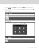
Table Of Contents
- Important Safety Information
- 1 GXT5 Description
- 2 Installation
- 3 Operating the UPS
- 4 Operation and Display Panel
- 5 Maintenance
- 6 Troubleshooting
- 7 Specifications
- Appendices

4.1 LED Indicators
The LEDs on the front-panel display indicate operation and alarm statuses of the UPS.
NOTE: When an alarm is indicated, an alarm message is logged. on page42, describes the alarm
messages you may see. When a fault is indicated, front-panel display list the fault, which are described
in
Table 6.2 on page55.
INDICATOR LED COLOR LED STATE INDICATES:
Run indicator Green
On UPS has output
Blinking Inverter is starting
Off UPS has no output
Alarm indicator
Yellow On Alarm occurs
Red On Fault occurs
None Off No alarm, no fault
Table 4.2 LED Functions
4.2 LCD Menu and Screens
The menu-driven LCD user interface lets you browse the UPS status, view operating parameters,
customize settings, control operation, and view alarm/event history. Use the function keys to navigate
through the menu, and view statuses or select settings in the screens.
4.2.1 Start-up and Flow Screens
At start-up, the UPS executes a system test and displays the Vertiv logo screen for about 10 seconds,
shown in
Figure 4.1 on page29. After the test completes, an overview screen shows status information,
the active (green) power path, and the non-working power path (gray).
NOTE: Figure 4.3 below, is an example flow screen and does not reflect the actual values that you may
see on your unit.
Figure 4.3 UPS Flow Screen
4 Operation and Display Panel
31