
User Manual

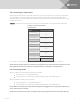
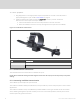
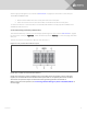
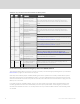
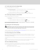
Table Of Contents
- Important Safety Information
- 1 GXT5 Description
- 2 Installation
- 3 Operating the UPS
- 4 Operation and Display Panel
- 5 Maintenance
- 6 Troubleshooting
- 7 Specifications
- Appendices

To make the cable for the REPO connection:
Figure 2.5 below, shows the cable required to make the connection. We recommend using 18AWG to
22AWG (0.82mm
2
to 0.33mm
2
) copper-core cable.
1. Remove the insulation from the end of two cables.
2. Insert the stripped end into the plug terminals 1 and 2 respectively, then press down the
terminals. Make sure that the cables are secure in the plug to prevent failure because of loose
contact.
To connect a UPS to the REPO switch
CAUTION: To maintain safety (SELV) barriers and electromagnetic compatibility, signal cables
should be shielded and run separately from power cables.
1. Connect one end of the cable to the remote switch, see Figure 2.5 below.
2. Remove the factory-installed jumper from pins 7 and 8 of the dry-contact port on the UPS
3. Connect the plug to pins 7 and 8.
Figure 2.5 Cable/Plug for Connecting REPOswitch to UPS REPO port
ITEM DESCRIPTION
1 Terminal 1
2 Terminal 2
3 Plug (connects to REPO port on UPS)
4 REPO switch
2.7.4 Connecting a USB Cable
The UPS includes a USB connector. See the appropriate figure for your model in
Rear Panels on page5,
for the location of the port.
The standard, B-type USB port connects the UPS to a network server or other computer system.
The USB port supports HID/CDC protocol. The CDC protocol is reserved for service software.
2 Installation
23