
User Manual

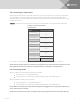
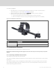
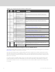
Table Of Contents
- Important Safety Information
- 1 GXT5 Description
- 2 Installation
- 3 Operating the UPS
- 4 Operation and Display Panel
- 5 Maintenance
- 6 Troubleshooting
- 7 Specifications
- Appendices

PORT
NO.
PORT
NAME
PIN
NO.
PIN NAME DESCRIPTION
1 Input 1
1
Disable/Battery mode
shutdown/Any mode
shutdown (Remote Comms
Shutdown)
Default: Disable, can be set via the LCD settings page. User can choose
dry contact as NO/NC. when NO, Pin 1 and Pin 2 are shorted, the
function is active. when NC, Pin 1 and Pin 2 are open, the function is
active.
2 Signal Ground Signal Ground
2 Input 2
3
Disable/Battery mode
shutdown/Any mode
shutdown (Remote Comms
Shutdown)
Default: Disable, can be set via the LCD settings page. User can choose
dry contact as NO/NC. when NO, Pin 1 and Pin 2 are shorted, the
function is active. when NC, Pin 1 and Pin 2 are open, the function is
active.
4 Signal Ground Signal Ground
3
Battery
Detection
5 EBC Detection
Default: Normally-Open (NO), automatically detects number of external-
battery cabinets when pins 5 and 6 are connected to the detection port,
see Installing External Battery Cabinets on page16.
6 EBC Detection
Default: Normally-Open (NO), automatically detects number of external-
battery cabinets when pins 5 and 6 are connected to the detection port,
see Installing External Battery Cabinets on page16.
REPO
REPO
Input
7 +5V REPO power supply, 5-Vdc 100-mA
8 REPO Coil -NC
NC, activated when Pin 7 and Pin 8 is open
NOTE: For details on REPOconnection and operation, see
Connecting a Remote Emergency Power-off (REPO) Switch below.
5 Output 5
9
Low Battery/Onbattery/
Onbypass/UPSfault
Default: Low battery, can be set via the LCD settings page. When the
system has a fault, short Pin 9 and Pin 10
10 Signal Ground Signal Ground
6 Output 6
11
Low Battery/Onbattery/
Onbypass/UPSfault
Default: UPS fault, can be set via the LCD settings page. When the
system has a fault, short Pin 11 and Pin 12
12 Signal Ground Signal Ground
Table 2.2 Dry-contact Connection and Pin-out Descriptions
2.7.3 Connecting a Remote Emergency Power-off (REPO) Switch
The UPS includes an EPO connection in the dry-contact port. See the appropriate figure for your model in
Rear Panels on page5, for the location of the port.
UPS ships with a REPO jumper installed, allowing the UPS to operate as a normally-closed switch system
(fail-safe). Opening the circuit disables the UPS. To connect a REPOswitch that opens the circuit to shut
down the rectifier and inverter and power-off the UPS, use a cable from the remote switch to plug into the
REPO-port on the UPS.
In normal conditions, the REPO switch cannot cut off the UPS input power. When the REPO switch trips,
the UPS generates an alarm and immediately cuts-off output power. When the emergency condition is
resolved, the UPS will not return to normal operation until you reset the REPO switch and manually power-
on the UPS.
Vertiv | Liebert® GXT5™ Installer/User Guide
22