
User Manual

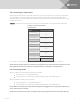
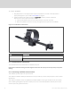
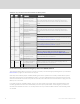
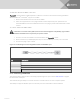
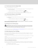
Table Of Contents
- Important Safety Information
- 1 GXT5 Description
- 2 Installation
- 3 Operating the UPS
- 4 Operation and Display Panel
- 5 Maintenance
- 6 Troubleshooting
- 7 Specifications
- Appendices

To connect equipment:
1. Plug equipment into the appropriate output receptacles on the rear of the UPS, see the
appropriate figure for your model in
Rear Panels on page5.
2. Install the cable-strain-relief fixtures, see Figure 2.3 below, to prevent accidental
disconnection of the input and output cables:
a. Insert the attachment end into the hole provided on the rear of the unit.
b. Place the cable(s) to secure in the loop, and tighten the loop around the cable(s).
Figure 2.3 Cable Strain-relief Fixture
ITEM DESCRIPTION
1 Power-cord loop
2 Fixture-attachment end
2.7 Communication Connections
The UPS offers several communication interfaces and ports.
NOTE: We recommend that signal-cable lengths be less than 10ft(3m), and are kept away from power
cabling.
2.7.1 Connecting IntelliSlot Communication
The IntelliSlot ports accepts two optional cards:
The Liebert® IntelliSlot™ Relay card (IS-RELAY) card provides dry-contact relay output for custom-wired
applications.
The Liebert® IntelliSlot™ Unity card (RDU101) provides SNMP monitoring of the UPS across the network
and/or building management system and lets you monitor external temperature, humidity and contact-
closure inputs using external sensors.
Vertiv | Liebert® GXT5™ Installer/User Guide
20