
User Manual

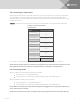
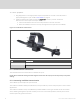
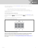
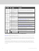
Table Of Contents
- Important Safety Information
- 1 GXT5 Description
- 2 Installation
- 3 Operating the UPS
- 4 Operation and Display Panel
- 5 Maintenance
- 6 Troubleshooting
- 7 Specifications
- Appendices

2.5 Connecting AC Input Power
Ensure that all the loads are turned Off. Prepare an input power supply that is properly protected by a
circuit breaker in accordance with national and local electrical codes. The wall receptacle must be
grounded. We recommend installing an upstream circuit breaker of the same series as the input circuit
breaker of the GXT5.
Table 2.1 below, lists the specifications of the input circuit breaker on the rear panel by UPS model
MODEL RATED CIRCUIT BREAKER
GXT5-750IRT2UXL
10 A
GXT5-750IRT2UXLE
GXT5-1000IRT2UXL
10 A
GXT5-1000IRT2UXLE
GXT5-1500IRT2UXL
10 A
GXT5-1500IRT2UXLE
GXT5-2000IRT2UXL
16 A
GXT5-2000IRT2UXLE
GXT5-3000IRT2UXL
20 A
GXT5-3000IRT2UXLE
GXT5-3KL620RT2UXL 20 A
GXT5-3KL630RT2UXL 20 A
Table 2.1 Input circuit breaker
specifications
To connect AC-input power, plug the input plug of the UPS into the input-power connection.
NOTE: If the input plug will serve as the disconnecting device, the wall socket/outlet must be near the
UPS and must be easily accessible, per the National Electric Code/NFPA 70 requirements.
2.6 Connecting Loads
750-Va to 2000-VA models have three groups of outlets:
• One group is not controlled (always On).
• Two groups are controlled with programmed responses or an SNMP network.
3000-A models have four groups of outlets:
• Two groups are not controlled (always On).
• Two groups are controlled with programmed responses or an SNMP network.
NOTE: When connecting load, verify that the equipment is plugged into the appropriate outlets if any
of the outlets will be controlled.
NOTE: Do not overload any output receptacle. Output cable length should not exceed 10m (32.8ft).
2 Installation
19