
User Manual

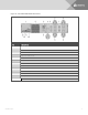

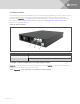

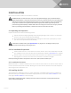

Table Of Contents
- Important Safety Information
- 1 GXT5 Description
- 2 Installation
- 3 Operating the UPS
- 4 Operation and Display Panel
- 5 Maintenance
- 6 Troubleshooting
- 7 Specifications
- Appendices

2.3.1 Tower Installation
To install the UPS as a tower:
1. Take the support bases out of the accessories box.
Figure 2.1 Support bases
NO. DESCRIPTION
1 Support bases
2
Spacers with connectors
NOTE: Three spacers are shown here. However, the number of spacers varies depending on your UPS
model and the number of battery cabinets in your system.
2. If optional, Liebert® external battery cabinets will be connected, take out the spacers shipped
with the battery cabinet.
3. Connect the spacers and the support bases as shown in Figure 2.1 above. Each GXT5 requires
2support bases, one in the front and one in the rear.
4. Place the GXT5 and any battery cabinets on the 2support bases.
2.3.2 Rack Installation
When installed in a rack enclosure, the GXT5 UPS and external battery cabinets (EBC) must be supported
by a shelf or rack-mount rails. Because different rack-mount options install differently, refer to the
installation instructions provided with the rack-mount kit.
CAUTION: The GXT5 is heavy. The UPS must be installed as near the bottom of a rack as
possible. If placed too high, it can make the rack top-heavy and prone to tipping over. For unit
weights, see Specifications on page57.
2.4 Installing External Battery Cabinets
Optional, external battery cabinets (EBC) may be connected in parallel to the UPS to provide additional
battery run time. For approximate battery run times with additional EBCs, see Battery Run Times on
page63.
External battery cabinets are placed on one side of the UPS in a tower configuration or stacked beneath
the UPS in a rack configuration. Up to 10 EBCs may be connected to the UPS, and up to 6 may be
detected using EBC-detection.
Vertiv | Liebert® GXT5™ Installer/User Guide
16