
Install Instructions

WARNING: Disconnect incoming power to
panel.
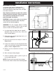
1. Isolate the fl oat by disconnecting one or both
of the fl oat leads from the fl oat terminals.
2. Place one ohmmeter lead on one of the fl oat
wires, and the other ohmmeter lead on the
other fl oat wire.
3. Place the ohmmeter dial to read ohms and
place on the R X 1 scale. With the fl oat in the
“off” position, the scale should read infi nity
(high resistance). Replace the fl oat if you do
not get this reading. With the fl oat in the ON
position, the scale should read nearly zero
(very low resistance). Replace the fl oat if you
do not get this reading.
NOTE: Readings may vary depending on the
length of wire and accuracy of the measuring
device.
Fuses
Check the continuity of the fuse. With power OFF,
pull the fuse out of the fuse block. With the ohm-
meter on the R X 1 scale, measure resistance. A
reading of infi nity indicates a blown fuse and must
be replaced. Replace fuse with same type, voltage
and amp rating.
Magnetic Contactor Coil
WARNING: Disconnect incoming power to
panel.
Check the coil by disconnecting one of the coil
leads. Measure the coil resistance by setting the
ohmmeter on the R X 1 scale. A defective coil will
read zero or infi nity, indicating a short or opened
coil respectively. Replace defective contactor with
same type.
NOTE: Readings may vary depending on the
accuracy of the measuring device.
Alarm Horn
Moving the test/
normal/silence
switch to the test
position or activat-
ing the alarm fl oat should turn on the alarm horn.
If the horn does not sound, replace horn with
same type.
Alarm Light
Moving the test/normal/silence switch to the test
position or activating the alarm fl oat should turn
on the alarm light. If the light does not activate,
replace light with same type.
Circuit Breaker (optional)
Check each pole of the circuit breaker for proper
resistance reading using the following procedure.
WARNING: Disconnect incoming power to
panel.
1. Isolate the circuit breaker by disconnecting
either line side or load side wires.
2. Place the ohmmeter leads across the corre-
sponding line and load terminals of each pole.
3. With the ohmmeter on the R X 1 scale and the
breaker in the OFF position, the reading should
be infi nity (very high resistance). With the
breaker in the ON position, the reading should
be nearly zero ohms (very low resistance). If
the readings are not as stated, replace the
circuit breaker with one of the same ratings.
NOTE: Readings may vary slightly depend-
ing on the accuracy of the measuring de-
vice.
Float Controls
Check the fl oats during their entire range of op-
eration. Clean, adjust, or replace damaged fl oats.
Checking the fl oat resistance - The fl oat resis-
tance can be measured to determine if the fl oat
is operating correctly or is defective. Use the fol-
lowing procedure to measure the fl oat resistance.
Troubleshooting
7203000B
- 5 -