
Install Instructions

Installation Instructions
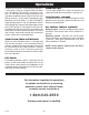
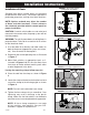
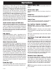
FIGURE 3
Clamp detail, mounting to Liberty Pumps “Quick Tree”:
Note: Approximate activation level of 1.5 inches (4 cm)
above or below horizontal.
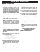
FIGURE 2: Clamp detail, mounting to pipe:
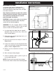
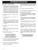
FIGURE 1: Float Locations
Float Locations
Off Float - 6” above pump inlet
On Float - 6” below basin
Alarm Float - 3” below basin
Installation of Floats
A standard single phase simplex panel is
designed to operate with three fl oats. These
fl oats operate pump stop, pump start, and high
level alarm functions.
Note: Options ordered may affect the number
of fl oats and their functions. Please reference
the schematic provided with the control
panel for proper installation.
CAUTION: If control switch cables are not wired
and mounted in the correct order, the pump
system will not function properly.
WARNING: Turn off all power before installing
fl oats in pump chamber. Failure to do so could
result in serious or fatal electrical shock.
1. Use fl oat label kit to label fl oats for specifi c
operation (stop, start, alarm, etc.). See sche-
matic for fl oat options.
2. Determine your normal operating level, as il-
lustrated in Figure 1.
3. Place the cord into the clamp as shown in
Figure 2 or 3.
4. Locate the clamp at the desired position from
step 2, and secure the clamp to the discharge
pipe as shown in Figure 2 or 3.
5. Make sure the movement of floats is not
restricted.
6. Wire switch per wiring diagram.
7. Check installation. Allow system to cycle to
insure proper operation.
NOTE: Do not install cord under hose clamp.
Do not install switch in direct line of incoming liquid.
7203000B
- 2 -