
Installation


6
LG CO
2
Sensor Installation Manual
Due to our policy of continuous product innovation, some specications may change without notication.
©LG Electronics U.S.A., Inc., Englewood Cliffs, NJ. All rights reserved. “LG” is a registered trademark of LG Corp.
1. Open the Case.
To open CO2 sensor case, insert a flat-head screwdriver in the slot (see right), and gently twist.
2. Remove the CO2 sensor Printed Circuit Board (PCB).
The installer needs to remove the PCB attached to the bottom part of the case before
wall-mounting the CO2 sensor. To detach, push the support tabs out that are holding the PCB, lift
the PCB up, and remove.
Figure 2: Removing the Cover.
INSTALLATION AND WIRING
3. Choose an installation location for the CO2 sensor.
General Dos
The CO2 sensor should be installed:
• In an occupied space that has air exchange from the ERV
• Where it can accurately detect the CO2 level of the space
• Four (4) to five (5) feet above the floor where its LED display can
be read easily (if CO2 sensor monitoring is required; possibly near
the zone controller)
• In an area with good air circulation
• Where the CO2 sensor is within reach of the ERV with the one (1) factory-supplied 33-foot extension
cable
General Don’ts
Do not install the CO2 sensor near or in:
• Drafts or dead spots behind doors and in corners
• An open window
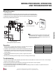
4. Wall-mount the CO2 sensor.
Using the bottom part of the case as a template, mark the area on the wall where the three (3) facto-
ry-supplied screws and the access hole for the hard-wired connection cable should go. Drill the holes,
then attach the bottom of the CO2 sensor case securely to the wall.
5. Reinsert the PCB and reattach the cover.
After wiring is complete (see Wiring), place the right side of the PCB under the guides on the case. Gently push the left side of the PCB
under the support tabs until it snaps in place, indicating it is secure.
Position the three guides (on the cover) at the bottom of the case, then push down on the top until the two hooks snap in place.
To detach the PCB from the
bottom cover, push the support
tabs out.
Figure 3: Push the Support Tabs Out.
Holes for the Three (3) Screws
Figure 4: Attaching the CO2
Sensor Case to the
Wall.
Wiring
The CO2 sensor PCB has a hard-wired connection cable ending in a female terminal. The factory-sup-
plied 33-foot male extension cable connects this cable to the CN-CO2 terminal on the ERV PCB. No
splicing or additional connections are required.
To avoid damaging the CO2 sensor PCB, place it in a clean secure
location while the backplate is being installed.
Figure 5: CO2 Sensor PCB.