
Installation


5
Installation
Due to our policy of continuous product innovation, some specications may change without notication.
©LG Electronics U.S.A., Inc., Englewood Cliffs, NJ. All rights reserved. “LG” is a registered trademark of LG Corp.
Factory-Supplied Parts
Introduction
The CO2 sensor is especially designed to work in conjunction with LG Energy Recovery Ventilators (ERVs). Real-time CO2 levels are detect-
ed and displayed on the sensor’s LCD. The CO2 sensor then sends the data to the LG ERV via the hard-wired connection cable coupled with
the supplied 33-foot extension cable. LG ERVs, using stand-alone embedded logic, will respond to CO2 changes in the surrounding ambient
air by applying demand control ventilation when its fan is set to Auto mode. Energy efficiency is increased, and indoor air quality can be
improved when ventilation air is introduced to the monitored space only as necessary.
INTRODUCTION, PARTS LIST, AND
SPECIFICATIONS
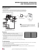
6-inch Hard-Wired
Connection Cable
CO2 Sensor
LCD
Yellow
LED
Part Quantity Image
33-foot Extension
Cable
One (1)
Mounting Screws Three (3)
Installation Manual One (1)
Table 1: Factory-Supplied Parts Table.
Figure 1: CO2 Sensor (Model No. PES-C0RV0).
Specications
For Use With ARVU053-063ZEA2 and ARVU093-123ZFA2 LG Energy Recovery Ventilators (ERV)
Power Supply 12V DC ±5%
Analog Output 0 to 5V DC
Measuring Range 0 to 2,000 ppm
Dimensions 4-1/16″ H x 3-1/4″ W x 1-1/4″ D
Net Weight 4 oz. (CO2 Sensor with its 6-inch Hard-Wired Cable Only)
Shipping Weight Approximately 1 lb.
The CO2 sensor does not work with interlock or slave operation with indoor units.
Specifications
Table 2: Specications Table.