Installation Manual for LG CO2 Sensor Model Number: PESC0RV0
Proprietary Data Notice This document, as well as all reports, illustrations, data, information, and other materials are the property of LG Electronics U.S.A., Inc., and are disclosed by LG Electronics U.S.A., Inc. only in confidence. Do not throw away, destroy, or lose this manual. Please read carefully and store in a safe place for future reference. Content familiarity required for proper installation.
SAFETY PRECAUTIONS The instructions below must be followed to prevent product malfunction, property damage, injury or death to the user or other people. Incorrect operation due to ignoring any instructions will cause harm or damage. The level of seriousness is classified by the symbols described below. TABLE OF symbols DANGER This symbol indicates an imminently hazardous situation which, if not avoided, will result in death or serious injury.
SAFETY PRECAUTIONS OPERATION DANGER Do not provide power to or operate the sensor if it is flooded or submerged. Always have the dealer or an authorized technician to service the sensor. Do not store or use flammable gas or combustibles near the sensor. Do not install the CO2 sensor (or its hard-wired and extension cables) in a location exposed to open flame or extreme heat. Do not touch the sensor with wet hands. Do not modify or extend the power supply cord.
Introduction, Parts List, and Specifications Introduction The CO2 sensor is especially designed to work in conjunction with LG Energy Recovery Ventilators (ERVs). Real-time CO2 levels are detected and displayed on the sensor’s LCD. The CO2 sensor then sends the data to the LG ERV via the hard-wired connection cable coupled with the supplied 33-foot extension cable.
Installation and Wiring 1. Open the Case. To open CO2 sensor case, insert a flat-head screwdriver in the slot (see right), and gently twist. Figure 2: Removing the Cover. 2. Remove the CO2 sensor Printed Circuit Board (PCB). The installer needs to remove the PCB attached to the bottom part of the case before wall-mounting the CO2 sensor. To detach, push the support tabs out that are holding the PCB, lift the PCB up, and remove.
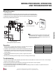
Wiring Procedure, Operation, and Troubleshooting Wiring Procedure 1. 2. 3. 4. Power down the ERV. Attach one male end of the extension cable to the female connection on the hard-wired cable. Attach the other male end of the extension cable to the CN-CO2 terminal on the ERV Main PCB. Reattach the CO2 sensor PCB to the bottom of the case (that has already been wall-mounted). Figure 6: Wiring from ERV PCB to CO2 Sensor.
Contact your local sales representative if you have any questions about the CO2 sensor or its installation. LG Electronics, U.S.A., Inc. Commercial Air Conditioning Division 11405 Old Roswell Road Alpharetta, Georgia 30009 www.lg-vrf.com LG Customer Information Center, Commercial Products 1-888-865-3026 USA Follow the prompts for commercial A/C products.