website http://www.lgservice.com INSTALLATION MANUAL FRANÇAIS LG Room Air Conditioner ENGLISH LG ESPAÑOL IMPORTANT • Please read this instruction manual completely before installing the product. • When the power cord is damaged, replacement should be performed by authorized personnel only. • Installation work must be performed in accordance with the national wiring standards by authorized personnel only. • Please retain this installation manual for future reference after reading it thoroughly.
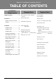
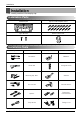
Room Air Conditioner Installation Manual TABLE OF CONTENTS Installation Requirements Safety Precautions............................4 Introduction ........................................7 Required Parts ❏ Four type "A" screws & plastic anchors ❏ Connecting cable Symbols used in this manual..........7 Features ...........................................7 ❏ Installation guide map Required Tools ❏ Level gauge ❏ Screw driver ❏ Electric drill ❏ Hole core drill [ø70mm(2.
IMPORTANT! Please read this instruction sheet completely before installing the product. This air conditioning system meets strict safety and operating standards. As the installer or service person, it is an important part of your job to install or service the system so it operates safely and efficiently. WARNING • Installation or repairs made by unqualified persons can result in hazards to you and others.
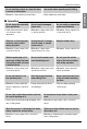
Safety Precautions Safety Precautions To prevent the injury of the user or other people and property damage, the following instructions must be followed. ■ Be sure to read before installing the air conditioner. ■ Be sure to observe the cautions specified here as they include important items related to safety. ■ Incorrect operation due to ignoring instruction will cause harm or damage. The seriousness is classified by the following indications.
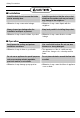
Safety Precautions Do not install the product at a place that there is concern of falling down. • Sharp edges may cause injury. ■ Operation Do not share the outlet with other appliances. • It will cause an electric shock or a fire due to heat generation. Take care so that the power cord may not be pulled during operation. • Otherwise, it may cause a fire or electrical shock. Take the power plug out if necessary, holding the head of the plug and do not touch it with wet hands.
Safety Precautions ■ Installation Install the drain hose to ensure that drain can be securely done. • Otherwise, it may cause water leakage. Always inspect gas leakage after the installation and repair of product. • Otherwise, it may cause the failure of product. Install the product so that the noise or hot wind from the outdoor unit may not cause any damage to the neighbors. • Otherwise, it may cause dispute with the neighbors. Keep level parallel in installing the product.
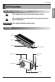
Introduction Introduction This symbol alerts you to the risk of electric shock. This symbol alerts you to hazards that may cause harm to the air conditioner. NOTICE This symbol indicates special notes.
Installation Installation Read carefully, and then follow step by step.
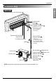
Installation Installation Map ENGLISH NOTICE Installation parts you should purchase. Installation plate Sleeve Bushing-Sleeve Putty(Gum Type Sealer) Bend the pipe as closely on the wall as possible, but be careful that it doesn't break. Air Discarge Operation Indication Lamps/ Signal Receptor Vinyl tape (Wide) Forced Operation Button Saddle • Apply after carrying out a drainage test. • To carry out the drainage test, remove the air filters and pour water into the heat exchanger.
Installation Confirm The Refrigerant 1. Check the quality label on the indoor and outdoor unit. 2. Make certain that the refrigerant is R-410A. NOTICE THIS PRODUCT CONTAINS R-410A REFRIGERANT 1) Different compressor oil - R-410A(Polyol ester) / R-22(Mineral). - Do not mix the existing mineral oil. - Do not apply used pipe, tools and gauges covered with the existing mineral oil. 2) Absorption of moisture -Compressor’s oil has the high absorption rate of moisture.
Installation Select the best Location 1. Do not have any heat or steam near the unit. 2. Select a place where there are no obstacles in front of the unit. More than 10cm(3.9in) More than 20cm(7.9in) 3. Make sure that condensation drainage can be conveniently routed away. More than 10cm(3.9in) 4. Do not install near a doorway. 5. Ensure that the interval between a wall and the left (or right) of the unit is more than 10cm(3.9in).
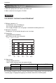
Installation Piping Length and Elevation LIQUID Standard Length m(ft) Max. Elevation B m(ft) Max. Length A m(ft) Additional Refrigerant g/m(oz/ft) 1/4" 7.5(25) 7(23) 30(98) 20(0.22) Pipe Size Capacity (Btu/h) GAS 30k 5/8" Indoor unit Outdoor unit Outdoor unit A B A Outdoor unit Indoor unit Oil trap B A Indoor unit B If piping length is more than 5m(16.4ft) Capacity is based on standard length and maximum allowance length is on the basis of reliability.
Installation Fixing Installation Plate 1. Mount the installation plate on the wall with type "A" screws. If mounting the unit on a concrete wall, use anchor bolts. • Mount the installation plate horizontally by aligning the centerline using a level. ENGLISH The wall you select should be strong and solid enough to prevent vibration Installation Plate Chassis Hook Type "A" screw 2. Measure the wall and mark the centerline.
Installation Flaring Work Main cause for gas leakage is due to defect in flaring work. Carry out correct flaring work in the following procedure. Cut the pipes and the cable. 1. Use the piping kit accessory or the pipes purchased locally. 2. Measure the distance between the indoor and the outdoor unit. Copper pipe Slanted Uneven Rough 90° 3. Cut the pipes a little longer than measured distance. 4. Cut the cable 1.5m(59.1in) longer than the pipe length. Pipe Burrs removal Reamer 1.
Installation Check 1. Compare the flared work with the figure by. Smooth all round Inside is shiny without scratches = Improper flaring = Even length all round Inclined Surface Cracked Uneven damaged thickness Connecting the Piping Indoor 1. Prepare the indoor unit's piping and drain hose for installation through the wall. 2. Remove the plastic tubing retainer(see the illustration by) and pull the tubing and drain hose away from chassis. 3.
Installation 4. Indoor unit installation Hook the indoor unit onto the upper portion of the installation plate.(Engage the two hooks of the rear top of the indoor unit with the upper edge of the installation plate.) Ensure that the hooks are properly seated on the installation plate by moving it left and right. Connecting cable Drain hose Press the lower left and right sides of the unit against the installation plate until the hooks engage into their slots(clicking sound).
Installation For left rear piping 1 2 Connecting cable 2. Insert the piping, drain hose, and the connecting cable into the piping hole. 3. Insert the connecting cable into the indoor unit. • Don't connect the cable to the indoor unit. • Make a small loop with the cable for easy connection later. Drain pipe 4. Tape the drain hose and the connecting cables. 5. Indoor unit installation • Hang the indoor unit from the hooks at the top of the installation plate. • Insert the spacer etc.
Installation Wrap the insulation material around the connecting portion. 1. Overlap the connection pipe heat insulation and the indoor unit pipe heat insulation material. Bind them together with vinyl tape so that there may be no gap. 2. Wrap the area which accommodates the rear piping housing section with vinyl tape. Plastic bands Insulation material Indoor unit piping Connection pipe Vinyl tape (wide) Wrap with vinyl tape Pipe Vinyl tape(narrow) Connecting cable 3.
Installation Installation Information. For left piping. Follow the instruction below. • Press on the upper side of clamp and unfold the tubing to downward slowly. Bad case • Following bending type from right to left may cause damage to the tubing.
Installation Outdoor Align the center of the pipings and sufficiently tighten the flare nut by hand. Finally, tighten the flare nut with torque wrench until the wrench clicks. • When tightening the flare nut with torque wrench, ensure the direction for tightening follows the arrow on the wrench. Outside diameter mm inch Ø6.35 1/4 Ø9.52 3/8 Ø12.7 1/2 Ø15.88 5/8 Ø19.05 3/4 20 Room Air Conditioner Torque kg.m 1.8~2.5 3.4~4.2 5.5~6.6 6.3~8.2 9.9~12.
Installation Connecting the Cables Connect the cable to the indoor unit by connecting the wires to the terminals on the control board individually according to the outdoor unit connection. (Ensure that the color of the wires of the outdoor unit and the terminal No. are the same as those of the indoor unit.) The earth wire should be longer than the common wires. The circuit diagram is not subject to change without notice.
Installation Outdoor 1. Remove the cover control from the unit by loosening the screw. Connect the wires to the terminals on the control board individually as the following. 2. Secure the cable onto the control board with the holder (clamper). 3. Refix the cover control to the original position with the screw. Outdoor unit Terminal block Over 5mm (0.2") Power supply cord Conduit panel Connecting cable Wiring Diagram Cover control NOTICE 1. Separately wire power supply cord and connecting cable. 2.
Installation Power supply cable How to connect wiring to the terminals Strip 10mm(3/8") Strand wire Round terminal Connecting cable Loosening the terminal block screw Fastening the wire tightly Connecting cable According to the confirmation of the above conditions, prepare the wiring as follows. 1. Never fail to have an individual power circuit specifically for the air conditioner. As for the method of wiring, be guided by the circuit diagram posted on the inside of control cover. 2.
Installation Checking the Drainage To check the drainage. 1. Pour a glass of water on the evaporator. Connecting area drain hose 2. Ensure the water flows through the drain hose of the indoor unit without any leakage and goes out the drain exit. Leakage checking Drain pan Drain hose Leakage checking Drain piping 1. The drain hose should point downward for easy drain flow. Downward slope 2. Do not make drain piping like the following.
Installation Forming the Piping Seal small openings around pipings with a gum type sealer. • If you want to connect an additional drain hose, the end of the drain outlet should be routed above the ground. Secure the drain hose appropriately. Taping Drain hose Pipings Connecting cable In cases where the outdoor unit is installed below the indoor unit perform the following. 1. Tape the piping, drain hose and connecting cable from down to up. 2.
Installation Air Purging Air purging The air and moisture remaining in the refrigerant system have undesirable effects as indicated below. 1. Pressure in the system rises. 2. Operating current rises. 3. Cooling(or heating) efficiency drops. 4. Moisture in the refrigerant circuit may freeze and block capillary tubing. 5. Water may lead to corrosion of parts in the refrigeration system. Therefore, after evacuating the system, take a leak test for the piping and tubing between the indoor and outdoor unit.
Installation Soap water method Liquid side ENGLISH 1. Remove the caps from the 2-way and 3-way valves. 2. Remove the service-port cap from the 3-way valve. 3. To open the 2-way valve turn the valve stem counterclockwise approximately 90°, wait for about 2~3 sec, and close it. 4. Apply a soap water or a liquid neutral detergent on the indoor unit connection or outdoor unit connections by a soft brush to check for leakage of the connecting points of the piping. 5.
Installation Test Running 1. Check that all tubing and wiring are properly connected. 2. Check that the gas and liquid side service valves are fully open. Prepare remote controller 1. Remove the battery cover by pulling it according to the arrow direction. 2. Insert new batteries making sure that the (+) and (–) of battery are installed correctly. 3. Reattach the cover by pushing it back into position. NOTICE • Use 2 AAA(1.5volt) batteries. Do not use rechargeable batteries.
Installation NOTICE PUMP DOWN This is performed when the unit is relocated or the refrigerant circuit is serviced. Pump Down means collecting all refrigerant into the outdoor unit without the loss of refrigerant. Be sure to perform Pump Down procedure in the cooling mode. Pump Down Procedure 1. Connect a low-pressure gauge manifold hose to the charge port on the gas side service valve. 2. Open the gas side service valve halfway and purge the air in the manifold hose using the refrigerant. 3.
Installation Installation guide at the seaside 1. Air conditioners should not be installed in areas where corrosive gases, such as acid or alkaline gas, are produced. 2. Do not install the product where it could be exposed to sea wind (salty wind) directly. It can result corrosion on the product. Corrosion, particularly on the condenser and evaporator fins, could cause product malfunction or inefficient performance. 3.
P/No.