
Installation Manual

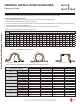
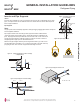
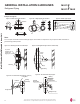
Table Of Contents
- Safety Instructions
- Introduction
- Unit Nomenclature
- General Data
- Specifications
- Typical Multi F/Multi F Max Systems
- Refrigerant Piping Requirements
- General Installation Guidelines
- Inspection
- Refrigerant Piping
- Piping Materials and Handling
- Piping Preparation
- Piping Connections
- Piping Insulation
- Drain Piping
- Electrical Wiring
- Power Wiring Specifications and Best Practices
- Power Wiring Specifications and Best Practices/Controller Options
- Indoor Unit Electrical Connections Guidelines
- Indoor Unit Electrical Connections Procedure
- Self Diagnosis Functions
- LG SIMS - Self Diagnosis Functions
- Optional Wall-Mounted Sensor and Controller
- Troubleshooting
- Cautions for Refrigerant leaks
- Installation CHECKLIST
27
Installation Manual
Due to our policy of continuous product innovation, some specifications may change without notification.
©LG Electronics U.S.A., Inc., Englewood Cliffs, NJ. All rights reserved. “LG” is a registered trademark of LG Corp.
MA
X
MUL
TI
F
MUL
TI
F
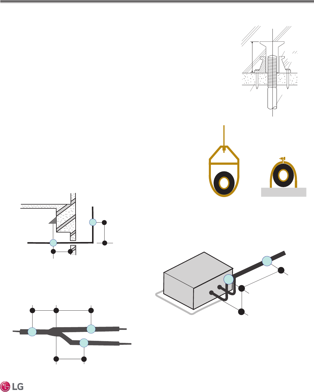
Pipe Supports
Figure 19: Installing an Insert Into
a Concrete Beam.
GENERAL INSTALLATION GUIDELINES
Refrigerant Piping
Inserts and Pipe Supports
Inserts
An insert can be installed into a floor or beam before the concrete sets so that fittings such as ducts,
pipes, or suspension bolts can be added at a later time. Decide where the inserts should be placed
before support installation.
Concrete Beam
Insert
Suspension Bolt
Anti-vibration Material
Nail
Figure 20: Pipe Hanger Details.
A
B
A + B ~ 12" – 19"
Max. 12" Max. 12"
Max. 12"
Figure 21: Typical Pipe Support Location—Change
in Pipe Direction.
Max. 12"
~ 12" – 19"
Pipe supports should never touch the pipe wall; supports should be installed outside
(around) the primary pipe insulation jacket. Insulate the pipe before installing the sup-
ports. Pipe supports are field-provided and must meet local code. If local codes do not
specify pipe support spacing, install pipe supports a maximum of 5 feet on center for
straight segments of pipe up to 3/4” outside diameter size.
Wherever the pipe changes direction, place a hanger within twelve (12) inches on one
side and within twelve to nineteen (12 to 19) inches of the bend on the other side. Sup-
port piping at indoor units as shown. Support Y-Branch fittings as shown.
Note:
The pipe system must be adequately supported to avoid pipe sagging. Sagging pipes become oil traps that
lead to equipment malfunction.
Figure 22: Pipe Support at Indoor Unit.
Figure 23: Pipe Support at Y-branch Fitting.