Inverter Single Wall Mounted (60Hz/R410A) 6RMI0-02A
Inverter Single-60Hz (R410A) 1. Models Line up .......................................................................................5 2. Nomenclature..........................................................................................8 3. Specifications .........................................................................................9 4. Dimensional drawings .........................................................................14 5. Wiring diagrams .........................................
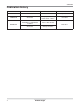
6RMI0-02A Publication history 2 Plb.No Outdoor Units Notes Publication in 6RMI0-01A All models Added N.A models Apr.2010 6RMI0-01B All models Change operation range Delete word “ Libero” Nov.2010 Add ʼ11 New models 6RMI0-02A LAN090HSV / LAN120HSV LAN180HSV / LAN240HSV LS307HV All models Change unit & Etc. Mar.
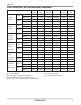
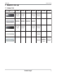
6RMI0-02A Test condition of international standard CLASSIFICATION Indoor Cooling Capacity Outdoor Indoor Heating Capacity Maximum Outdoor Indoor Cooling Operating Outdoor Maximum Indoor Heating Operating Enclosure Outdoor Indoor Sweat / Condensate Outdoor Disposal Freeze-up/ Indoor Low Temperature Outdoor KSC 9306 ISO 5151 ARI 210/240 AHAM AS 1861.1 SSA 385 DB°C(°F) 27.0 27.0 26.7(80) 26.7(80) 27.0 29.0 WB°C(°F) 19.5 19.0 19.4(67) 19.4(67) 19.0 19.0 DB°C(°F) 35.
6RMI0-02A General Description Split type of Air conditioners are known by the category name of Wall Mounted Type of units.These units can be easily installed in a small space and have exceptional Cooling capacity.Designed for Low-noise operation,it ensures a pleasant air conditioned environment. LG Offers various types of units to its customers to suit for the best application and requirement.
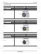
RMI0-02A Models line up 1. Models Line up 1.1 Indoor Unit kW (kBtu/h) Indoor Type 2.63(9) 3.51(12) 4.68(16) ASNW093BRU1 ASNW123BRU1 (LAN090HSV) (LAN120HSV) 5.27(18) 7.03(24) 8.79(30) 10.
Models line up 6RMI0-02A 1.2 Outdoor Unit Heat pump Total capacity index of connectable indoor units Power supply kW kBtu/h ASUW093B1U1(LSU091HSV) ASUW093BRU1 (LAU090HSV) ASUW123B1U1(LSU121HSV) ASUW123BRU1 (LAU120HSV) 2.63 9 3.51 12 1Φ / 208~230V / 60Hz Chassis UL2 Heat pump Total capacity index of connectable indoor units Power supply kW kBtu/h ASUW163C2U1(LSU161HSV) ASUW1838UH1(LAU186HV) 4.68 16 5.
6RMI0-02A Models line up Heat pump Total capacity index of connectable indoor units Power supply kW kBtu/h ASUW243DGU1(LSU240HSV) ASUW243CRU1 (LAU240HSV) 5.27 18 7.03 24 1Φ / 208~230V / 60Hz Chassis UE1+ ASUW2435SZ1(LSU246HV), ASUW2438UH1(LAU246HV) Heat pump Total capacity index of connectable indoor units Power supply kW kBtu/h ASUW303DGH1(LSU306HV) 7.03 24 8.
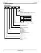
Nomenclature 6RMI0-02A 2.
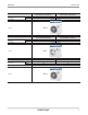
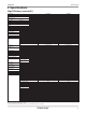
6RMI0-02A Specifications 3. Specifications High Efficiency Inverter(#1) Sales Model Models Cooling Capacity Heating Capacity Power Input Running Current Starting Current EER SEER HSPF Power Supply Power Factor Air Flow Rate Cooling Cooling/Heating Cooling/Heating Indoor,Max Outdoor,Max Dehumidification Sound Level Indoor,H/M/L Outdoor,Max Refrigerant & Charge (at 7.5 m) Additional Refrigerant charge Compressor Type Model Motor Type Oil Type Oil Charge O.L.P.
Specifications 6RMI0-02A Sales Model Models Cooling Capacity Heating Capacity Power Input Running Current Starting Current EER SEER HSPF Power Supply Power Factor Air Flow Rate Cooling Cooling/Heating Cooling/Heating Indoor,Max Outdoor,Max Dehumidification Sound Level Indoor,H/M/L Outdoor,Max Refrigerant & Charge (at 7.5 m) Additional Refrigerant charge Compressor Type Model Motor Type Oil Type Oil Charge O.L.P.
6RMI0-02A Specifications Artcool Inverter(#1) Sales Model Models Cooling Capacity Heating Capacity Power Input Running Current Starting Current EER SEER HSPF Power Supply Air Flow Rate Cooling Cooling/Heating Cooling/Heating Indoor,Max Outdoor,Max Dehumidification Sound Level Indoor,H/M/L Outdoor,Max Refrigerant & Charge (at 7.5 m) Additional Refrigerant charge Compressor Type Model Motor Type Oil Type Oil Charge O.L.P.
Specifications 6RMI0-02A Artcool Inverter(#2) Sales Model Models Cooling Capacity Heating Capacity Power Input Running Current Starting Current EER SEER HSPF Power Supply Power Factor Air Flow Rate Cooling Cooling/Heating Cooling/Heating Indoor,Max Outdoor,Max Dehumidification Sound Level Indoor,H/M/L Outdoor,Max Refrigerant & Charge (at 7.5 m) Additional Refrigerant charge Compressor Type Model Motor Type Oil Type Oil Charge O.L.P.
6RMI0-02A Specifications Inverter(#1) Sales Model Models Cooling Capacity Heating Capacity Power Input Running Current Starting Current EER SEER HSPF Power Supply Power Factor Air Flow Rate Cooling Cooling/Heating Cooling/Heating Indoor,Max Outdoor,Max Dehumidification Sound Level Indoor,H/M/L Outdoor,Max Refrigerant & Charge (at 7.5 m) Additional Refrigerant charge Compressor Type Model Motor Type Oil Type Oil Charge O.L.P.
Left rear piping Unit Outline Inverter Single 175(6.9) 133(5.2) 442(17.4) Installation Plate 5 Place a level on raised tab 442(17.4) 4 3 217(8.5) 95(3.7) Ø70(2.8) 159.5(6.3) 210(8.3) 2 [Unit: mm (inch)] 210(8.3) Right rear piping 59.5(2.3) 23(0.9) 285(11.2) 14 Ø70(2.8) 1 885(34.8) CHASSIS CODE : SB WALL MOUNTED Dimensional drawings 6RMI0-02A 4. Dimensional drawings 4.
Inverter Single Left rear piping Ø70(2.8) 105(4.1) 69(2.7) Unit Outline 460(18.1) Measuring Tape Hanger Measuring Tape Installation Plate Place a level on raised tab 1030(40.6) 570(22.4) 250(9.8) 325(12.8) 56(2.2) 207(8.1) Right rear piping Ø70(2.8) 4 [Unit: mm (inch)] 250(9.
Inverter Single 77(3.0) 107(4.2) 1 567(22.3) 354(13.9) 912(35.9) 51(2.0) 5 50(2.0) 171(6.7) 282(11.1) 16 165(6.5) 2 3 282(11.1) 53(2.1) 4 [Unit: mm (inch)] 51(2.0) Part Name Knockout hole For pipe and cable Remark CHASSIS CODE: SE 1. Unit should be installed in compliance with the installation manual in the product box. 2. Unit shall be grounded in accordance with the local regulations or applicable national codes. 3. The Unit is powered from the outdoor unit.
45(1.8) 140(5.5) 188(7.4) Ø70(2.8) 926(36.5) 1107(43.6) 5 Ø70(2.8) 221(8.7) 65(2.6) 58(2.3) 48(1.9) 122(4.8) 175(6.9) 296(11.7) Inverter Single 45(1.8) 1 2 93(3.7) 63(2.5) [Unit: mm (inch)] 200(7.9) 53(2.1) 4 10(0.4) 299(11.8) 3 Note For pipe and cable Remark CHASSIS CODE: S8 1. The unit should not be installed in a closed area. 2. In an area or space having no proper circulation, an air guide should be installed on the outdoor side.
1 1090(42.9) 53.2(2.1) 117.6(4.6) 2 3 Inverter Single 82.6(3.3) 107(4.2) 48.5(1.9) 53(2.1) 300(11.8) 4 5 [Unit: mm (inch)] 567.5(22.3) 345(13.6) 5(0.2) 180(7.1) 300(11.8) 18 180(7.1) 178(7) CHASSIS CODE : S5 Dimensional drawings 6RMI0-02A 35(1.
Inverter Single 858(33.8) 780(30.7) 60(2.4) 210(8.3) 335(13.2) 1209(47.6) 60(2.4) 346(13.6) [Unit: mm (inch)] 205(8.1) 60(2.4) CHASSIS CODE : SD 6RMI0-02A Dimensional drawings 19 65(2.
277(10.9) 558(22.0) 1 Ø464(18.3) 106(4.2) 353(13.9) 54(2.1) 154(6.1) 70(2.8) 20 Inverter Single 207(8.1) 770(30.3) 2 3 4 5 [Unit: mm (inch)] 288(11.3) CHASSIS CODE : UL2 Dimensional drawings 6RMI0-02A 4.2 Outdoor Units 267(10.5) 530(20.9) 545(21.
301(11.9) Ø531(20.9) 546(21.5) 319(12.6) 630(24.8) 655(25.8) 55(2.2) 160(6.3) 1 360(14.2) 79(3.1) 870(34.3) 320(12.
267 545(21.5) 22 275(10.8) 770(34.3) Ø450(17.7) 518(20.4) 56(2.2) 1 5 Inverter Single 2 3 4 [Unit: mm (inch)] 245(9.6) CHASSIS CODE : UL Dimensional drawings 6RMI0-02A 285(11.2) 261(10.
Inverter Single 319(12.6) 25(1) 301(11.9) Ø531(20.9) 546(21.5) 1 160(6.3) 800(31.5) 360(14.2) 55(2.2) 76(3) 79(3.1) 870(34.3) 5 320(12.
320(12.6) 800(31.5) 783(30.8) 24 333(13.1) Ø531(20.9) 546(21.5) 55(2.2) 160(6.3) 360(14.2) 50(2) 870(34.3) 320(12.6) [Unit: mm (inch)] No. 1 2 3 4 5 6 CHASSIS CODE : UE1+ Part Name Air discharge grille /I[ XQXM KWVVMK\QWV 4QY]QL XQXM KWVVMK\QWV 8W_MZ + ^IT^M KW^MZ Dimensional drawings 6RMI0-02A Inverter Single 80(3.1) 392(15.
6RMI0-02A Wiring diagrams 5. Wiring diagrams 5.
Wiring diagrams 6RMI0-02A Models: ASNW093ERH1(LAN096HV),ASNW123ERH1(LAN126HV) Models: ASNW1838RH1(LAN186HV), ASNW2438RH1(LAN246HV) 26 Inverter Single
6RMI0-02A Wiring diagrams Models: ASUW2435SZ1(LSU246HV) Models: ASNW303DGH1(LSN306HV) Inverter Single 27
Wiring diagrams 6RMI0-02A Models: ASNW243DGU1(LS240HSV), ASNW363DGU1(LS360HV) 28 Inverter Single
6RMI0-02A Wiring diagrams 6.
Wiring diagrams 6RMI0-02A Models: ASUW183C2U2(LSU181HSV),ASUW243DGU1(LSU240HSV),ASUW363DGU1(LSU360HV) Models: ASUW093EUH1(LAU096HV),ASUW123EUH1(LAU126HV) 30 Inverter Single
6RMI0-02A Wiring diagrams Models: ASUW1838UH1(LAU186HV), ASUW2438UH1(LAU246HV), ASUW2435SZ1(LSU246HV) Models: ASUW303DGH1(LSU306HV) Inverter Single 31
Refrigerant cycle diagram 6RMI0-02A 6. Refrigerant cycle diagram Models : AS-W093B1U1(LS091HSV), AS-W123B1U1(LS121HSV) Indoor Unit Outdoor Unit Liquid Side EEV 2-Way Valve Th2 Th1 Th4 Heat Exchanger (Evaporator) Heat Exchanger (Condenser) Th3 Th7 Th6 Gas Side 3-Way Valve Reversing Valve Accumulator Th5 Cooling Heating Compressor LOC.
6RMI0-02A Refrigerant cycle diagram Models : AS-W163C2U1(LS161HSV), AS-W183C2U2(LS181HSV), AS-W243DGU1(LS240HSV), AS-W363DGU1(LS360HV) Indoor Unit Outdoor Unit Liquid Side EEV 2-Way Valve Th2 Th1 Th4 Heat Exchanger (Evaporator) Heat Exchanger (Condenser) Th8 Th9 Th3 Th7 Gas Side 3-Way Valve Reversing Valve Accumulator Th5 Th6 Cooling Heating Compressor LOC.
Refrigerant cycle diagram 6RMI0-02A Models : AS-W093ERH1(LA096HV),AS-W123ERH1(LA126HV) Indoor Unit Outdoor Unit Liquid Side EEV 2-Way Valve Th2 Th1 Heat Exchanger (Evaporator) Heat Exchanger (Condenser) Th5 Th4 Gas Side 3-Way Valve Reversing Valve Accumulator Th3 Compressor LOC.
6RMI0-02A Refrigerant cycle diagram Modes : AS-W1838RH1(LA186HV), AS-W2438RH1(LA246HV), AS-W2435SZ1(LS246HV) Indoor Unit Outdoor Unit Liquid Side EEV 2-Way Valve Th2 Th1 Heat Exchanger (Evaporator) Heat Exchanger (Condenser) Th4 Th3 Th5 Gas Side Reversing Valve Accumulator 3-Way Valve Th6 Th7 Compressor LOC.
Refrigerant cycle diagram 6RMI0-02A Models : AS-W303DGH1(LS306HV) INDOOR UNIT OUTDOOR UNIT LIQUID SIDE Th2 EEV 3-WAY VALVE Th5 Th6 Th1 HEAT EXCHANGE (EVAPORATOR) HEAT EXCHANGE (CONDENSER) Th3 GAS SIDE 3-WAY VALVE ACCUMU LATOR Th9 Constant COMPRESSOR LOC.
6RMI0-02A Capacity tables 7. Capacity tables 7.1 Cooling Capacity AS-W093B1U1(LS091HSV) Outdoor Air Temperature : DB°C(℉) Indoor Air Temperature WB°C(°F) DB°C(°F) 14(57.2) 20(68) 16(60.8) 22(71.6) 18(64.4) 25(77) 19(66.2) 27(80.6) 22(71.6) 30(86) 24(75.2) 32(89.6) 20(68) TC 2.59 2.75 2.91 2.99 3.23 3.39 25(77) PI 0.37 0.50 0.54 0.55 0.55 0.55 TC 2.48 2.63 2.79 2.87 3.11 3.27 SHC 2.36 2.32 2.27 2.26 2.14 2.07 32(89.6) PI 0.39 0.51 0.55 0.55 0.56 0.57 TC 2.32 2.48 2.64 2.72 2.96 3.11 SHC 2.41 2.
Capacity tables 6RMI0-02A AS-W163C2U1(LS161HSV) Outdoor Air Temperature : DB°C(℉) Indoor Air Temperature WB°C(°F) DB°C(°F) 14(57.2) 20(68) 16(60.8) 22(71.6) 18(64.4) 25(77) 19(66.2) 27(80.6) 22(71.6) 30(86) 24(75.2) 32(89.6) 20(68) TC 4.69 4.98 5.26 5.41 5.84 6.13 PI 0.72 0.97 1.05 1.06 1.06 1.06 TC 4.48 4.77 5.06 5.20 5.63 5.92 SHC 4.03 3.96 3.87 3.86 3.65 3.54 32(89.6) PI 0.75 0.98 1.06 1.07 1.09 1.10 TC 4.21 4.49 4.78 4.92 5.35 5.64 SHC 4.12 4.04 3.95 3.94 3.73 3.62 35(95) PI 1.01 1.19 1.25 1.
6RMI0-02A Capacity tables AS-W243DGU1(LS240HSV) Outdoor Air Temperature : DB°C(℉) Indoor Air Temperature WB°C(°F) DB°C(°F) 14(57.2) 20(68) 16(60.8) 22(71.6) 18(64.4) 25(77) 19(66.2) 27(80.6) 22(71.6) 30(86) 24(75.2) 32(89.6) 20(68) TC 6.32 6.71 7.10 7.30 7.88 8.27 PI 0.97 1.32 1.43 1.44 1.44 1.43 TC 6.05 6.44 6.82 7.02 7.60 7.99 SHC 5.38 5.29 5.17 5.16 4.87 4.73 32(89.6) PI 1.02 1.33 1.43 1.45 1.48 1.49 TC 5.68 6.07 6.45 6.64 7.22 7.61 SHC 5.50 5.40 5.29 5.27 4.98 4.83 35(95) PI 1.36 1.61 1.69 1.
Capacity tables 6RMI0-02A AS-W123ERH1(LA126HV) Outdoor Air Temperature : DB°C(℉) Indoor Air Temperature WB°C(°F) DB°C(°F) 14(57.2) 20(68) 16(60.8) 22(71.6) 18(64.4) 25(77) 19(66.2) 27(80.6) 22(71.6) 30(86) 24(75.2) 32(89.6) 20(68) TC 3.39 3.60 3.81 3.91 4.23 4.44 PI 0.64 0.87 0.94 0.95 0.95 0.94 TC 3.25 3.45 3.66 3.76 4.08 4.28 SHC 2.40 2.36 2.31 2.30 2.17 2.11 32(89.6) PI 0.67 0.88 0.94 0.96 0.97 0.98 TC 3.05 3.25 3.46 3.56 3.87 4.08 SHC 2.45 2.41 2.36 2.35 2.22 2.16 35(95) PI 0.90 1.06 1.11 1.
6RMI0-02A Capacity tables AS-W2438RH1(LA246HV) Outdoor Air Temperature : DB°C(℉) Indoor Air Temperature WB°C(°F) DB°C(°F) 14(57.2) 20(68) 16(60.8) 22(71.6) 18(64.4) 25(77) 19(66.2) 27(80.6) 22(71.6) 30(86) 24(75.2) 32(89.6) 20(68) TC 6.95 7.38 7.81 8.02 8.66 9.09 25(77) PI 1.44 1.95 2.11 2.13 2.13 2.12 TC 6.65 7.08 7.50 7.71 8.35 8.78 SHC 4.92 4.83 4.73 4.72 4.46 4.32 32(89.6) PI 1.50 1.96 2.12 2.15 2.19 2.20 TC 6.24 6.67 7.09 7.30 7.94 8.36 SHC 5.03 4.94 4.83 4.82 4.55 4.42 35(95) PI 2.01 2.
Capacity tables 6RMI0-02A AS-W303DGH1(LS306HV) Outdoor Air Temperature : DB°C(℉) Indoor Air Temperature WB°C(°F) DB°C(°F) 14(57.2) 20(68) 16(60.8) 22(71.6) 18(64.4) 25(77) 19(66.2) 27(80.6) 22(71.6) 30(86) 24(75.2) 32(89.6) 20(68) TC 7.59 8.06 8.52 8.76 9.46 9.93 25(77) PI 1.76 2.38 2.57 2.60 2.60 2.59 TC 7.26 7.72 8.19 8.42 9.12 9.58 SHC 5.77 5.66 5.54 5.53 5.22 5.07 32(89.6) PI 1.83 2.40 2.59 2.63 2.67 2.70 TC 6.82 7.28 7.74 7.97 8.67 9.13 SHC 5.89 5.79 5.66 5.65 5.33 5.18 35(95) PI 2.46 2.
6RMI0-02A Capacity tables 7.2 Heating Capacity AS-W093B1U1(LS091HSV) Indoor Air Temperature DB°C(℉) 16(60.8) 18(64.4) 20(68) 21(69.8) 22(71.6) 24(75.2) Outdoor Air Temperature : WB°C(℉) -15(5) TC 2.38 2.36 2.34 2.34 2.33 2.31 PI 0.67 0.68 0.69 0.70 0.71 0.72 -10(14) TC 2.51 2.50 2.50 2.50 2.50 2.48 -5(23) PI 0.65 0.67 0.69 0.70 0.70 0.73 TC 2.72 2.72 2.72 2.72 2.72 2.69 PI 0.68 0.70 0.72 0.73 0.74 0.76 0(32) TC 2.90 2.90 2.89 2.89 2.88 2.86 PI 0.73 0.75 0.77 0.78 0.79 0.81 6(42.8) TC 3.22 3.
Capacity tables 6RMI0-02A AS-W243DGU1(LS240HSV) Indoor Air Temperature DB°C(℉) 16(60.8) 18(64.4) 20(68) 21(69.8) 22(71.6) 24(75.2) Outdoor Air Temperature : WB°C(℉) -15(5) TC 6.08 6.02 5.98 5.97 5.96 5.88 PI 1.63 1.65 1.68 1.70 1.72 1.76 -10(14) TC 6.40 6.39 6.39 6.39 6.39 6.33 -5(23) PI 1.59 1.63 1.67 1.70 1.72 1.77 TC 6.94 6.95 6.95 6.95 6.95 6.86 PI 1.66 1.71 1.76 1.79 1.81 1.86 0(32) TC 7.41 7.40 7.39 7.37 7.35 7.29 PI 1.79 1.84 1.89 1.91 1.94 1.98 6(42.8) TC 8.22 8.17 8.09 8.04 7.98 7.
6RMI0-02A Capacity tables AS-W2438RH1(LA246HV) Indoor Air Temperature DB°C(℉) 16(60.8) 18(64.4) 20(68) 21(69.8) 22(71.6) 24(75.2) Outdoor Air Temperature : WB°C(℉) -15(5) TC 5.95 5.89 5.85 5.83 5.82 5.75 PI 2.36 2.40 2.44 2.47 2.49 2.55 -10(14) TC 6.26 6.25 6.25 6.25 6.25 6.19 -5(23) PI 2.31 2.36 2.43 2.46 2.49 2.56 TC 6.78 6.79 6.79 6.79 6.79 6.71 PI 2.41 2.48 2.55 2.59 2.63 2.70 0(32) TC 7.24 7.24 7.22 7.21 7.19 7.13 PI 2.59 2.67 2.74 2.77 2.81 2.87 6(42.8) TC 8.04 7.99 7.91 7.86 7.80 7.
Capacity coefficient factor 6RMI0-02A 8. Capacity coefficient factor Cooling Capacity(%) 100 18K 9K,12K 24K,30K 90 80 70 7.5(24.6) 15(49.2) 30(98.4) 50(164) Total Pipe Length[m(ft)] Heating Capacity(%) 100 18K 9K,12K 24K,30K 90 80 70 7.5(24.6) 15(49.2) 30(98.
6RMI0-02A Capacity coefficient factor High Efficiency models Cooling Capacity(%) 110 105 100 95 90 85 80 75 70 2(6.6) 7.5(24.6) 20(65.6) Total Pipe Length[m(ft)] Heating 110 Capacity(%) 105 100 95 90 85 80 75 70 2(6.6) 7.5(24.6) 20(65.
Capacity coefficient factor 6RMI0-02A Models Max. Pipe Length[m(ft)] Max. Elevation[m(ft)] Additional Refrigerant[g/m(oz/ft)] AS-W093B1U1(LS091HSV) AS-W123B1U1(LS121HSV) AS-W163C2U1(LS161HSV) AS-W183C2U2(LS181HSV) AS-W243DGU1(LS240HSV) AS-W093ERH1(LA096HV) AS-W123ERH1(LA126HV) AS-W1838RH1(LA186HV) AS-W2438RH1(LA246HV) AS-W2435SZ1(LS246HV) AS-W303DGH1(LS306HV) AS-W363DGU1(LS360HV) 20(65.6) 20(65.6) 20(65.6) 30(98.4) 30(98.4) 15(49.2) 15(49.2) 15(49.2) 30(98.4) 30(98.4) 30(98.4) 30(98.4) 10(32.
6RMI0-02A Operation range 9. Operation range Cooling Heating 46(115°F) Operative Outdoor Unit [°C DB] 24(75°F) Continuous operation 18(64°F) -5(23°F) Outdoor Unit [°C DB] Low Ambient Operation Operative Warming up Operation 43(109°F) Continuous operation -10(14°F) Operative -10(14°F) -15(5°F) 18(64°F) 32(90°F) 16(61°F) Indoor Unit [°C DB] 30(86°F) Indoor Unit [°C DB] Operative: Intermittent operation due to the operational conditions (indoor/outdoor temperature, humidity, load etc.
Operation range 6RMI0-02A Cooling Heating 46(115°F) Operative Outdoor Unit [°C DB] 24(75°F) Continuous operation Outdoor Unit [°C DB] 18(64°F) Low Ambient Operation Warming up Operation 43(109°F) Continuous operation -10(14°F) Operative -10(14°F) -15(5°F) 18(64°F) 32(90°F) 16(61°F) Indoor Unit [°C DB] 30(86°F) Indoor Unit [°C DB] Operative: Intermittent operation due to the operational conditions (indoor/outdoor temperature, humidity, load etc.
6RMI0-02A Air flow and temperature distributions(reference data) 10. Air flow and temperature distributions(reference data) 2.63 kW (9kBtu/h) Cooling Heating Discharge angle:45° Discharge angle:50° Air velocity [ft/s] Air velocity [ft/s] 8.9ft 8.9ft 6.6ft 6.6ft 3.9 3.3 3.3 3.3ft 3.3ft 2.5 2.5 1.6 16.4ft 13.1ft 9.8ft 1.6 6.6ft 3.3ft 0ft 0ft Temperature [˚F] 16.4ft 13.1ft 9.8ft 6.6ft 3.3ft 0ft Temperature [˚F] 8.9ft 8.9ft 6.6ft 6.6ft 3.3ft 73.4 16.4ft 13.1ft 77 9.8ft 3.
Air flow and temperature distributions(reference data) 6RMI0-02A High Efficiency 2.63 kW (9kBtu/h) Cooling Heating Discharge angle:45° Discharge angle:50° AirVelocity [ft/s] AirVelocity [ft/s] 8.9ft 8.9ft 6.6ft 6.6ft 1.21.2 3.9 3.31.0 1.0 1.0 3.3 1.0 3.3ft 3.3ft 0.75 0.75 2.5 2.5 0.75 0.75 1.60.5 0.5 0.5 0.5 1.6 0ft 16.4ft 13.1ft 9.8ft 6.6ft 3.3ft 0ft Temperature [°F] 0ft 16.4ft 13.1ft 9.8ft 6.6ft 3.3ft 0ft Temperature [°F] 8.9ft 8.9ft 6.6ft 6.6ft 3.3ft 73.4 2323 3.
6RMI0-02A Sound level 11. Sound levels 11.1 Indoor Units Overall Notes: - Sound measured at 1m away from the center of the unit. - Data is valid at free field condition. - Data is valid at nominal operation condition. - Reference accoustic pressure 0dB=20Pa. - Sound level will vary depending on a range of factors such as the construction(acoustic absorption coefficient) of particular room in which the equipment is installed. - The operating conditions are assumed to be standard. 1m 0.
Sound level 6RMI0-02A 80 70 70 50 40 30 80 Octave Band Sound Pressure Level (dB re 20µPa ) 80 60 ASNW2438RH1(LAN246HV) ASNW2435SZ1(LSN246HV) ASNW1838RH1(LAN186HV) Octave Band Sound Pressure Level (dB re 20µPa ) Octave Band Sound Pressure Level (dB re 20µPa ) ASNW123ERH1(LAN126HV) 60 50 40 30 70 60 50 40 30 20 20 20 Approximate Hearing Threshold 10 63 10 10 63 125 250 500 1000 2000 4000 63 8000 250 500 1000 2000 4000 8000 ASNW303DGH1(LSN306HV) ASNW363DGU1(LSN360
6RMI0-02A Sound level 11.2 Outdoor Units Overall Notes: - Sound measured at 1m away from the center of the unit. - Data is valid at free field condition. - Data is valid at nominal operation condition. - Reference accoustic pressure 0dB=20Pa. - Sound level will vary depending on a range of factors such as the construction(acoustic absorption coefficient) of particular room in which the equipment is installed. - The operating conditions are assumed to be standard.
Sound level 6RMI0-02A ASUW2438UH1(LAU246HV) ASUW2435SZ1(LSU246HV) ASUW1838UH1(LAU186HV) NC-65 60 NC-60 NC-55 50 NC-50 NC-45 40 NC-40 NC-35 30 NC-30 NC-25 Approximate Hearing Threshold 63 70 NC-65 60 NC-60 NC-55 50 NC-50 NC-40 250 500 1000 2000 4000 NC-35 30 NC-30 NC-25 20 Approximate Hearing Threshold NC-15 125 NC-45 40 NC-20 10 80 63 ASUW363DGU1(LSU360HV) ASUW303DGU1(LSU307HV) 125 250 500 1000 2000 4000 8000 NC-65 60 NC-60 NC-55 50 NC-50 NC-45 40 NC-40 NC-35
6RMI0-02A Remote controller 12. Remote controller Wireless Remote Controller The controls will look like the following. ON/OFF BUTTON Used to turn off/on the unit. Signal transmitter OPERATION MODE SELECTION BUTTON Used to select the operation mode. ROOM TEMPERATURE SETTING BUTTONS Used to select the room temperature. INDOOR FAN SPEED SELECTION BUTTON Used to select fan speed in six steps low, medium-low, medium, medium-high, high and natural wind.
Remote controller 6RMI0-02A The controls will look like the following. Signal transmitter - Optional1 SLEEP MODE AUTO BUTTON Used to set sleep mode auto operation. - Optional2 JET COOL BUTTON Used to start or stop the speed cooling. The Jet Cool operates fan in super high speed in cooling mode.
6RMI0-02A Remote controller Wireless Remote Controller Control Display panel screen Display screen Description Plasma button*: Purifies the air by removing particles that enter the indoor unit. a F l = Sleep mode auto button*: Sets the sleep mode auto operation. e y Temperature adjustment buttons: Adjusts the room temperature when cooling and heating. d - On/Off button: Turns the power on/off. fan speed button: Adjusts the fan g 7 v Indoor speed.
Remote controller 6RMI0-02A 9 12 17 19 18 14 1. START/STOP BUTTON Used to turn off/on the unit. 2. OPERATION MODE SELECTION BUTTON Used to select the operation mode. 3. ROOM TEMPERATURE SETTING BUTTONS Used to select the room temperature. 4. INDOOR FAN SPEED SELECTOR BUTTON Used to select fan speed in four steps low, medium, high and CHAOS. 5. JET COOL/HEAT BUTTON Used to start or stop the speed cooling/heating. (It operates fan in super high speed) 6.
6RMI0-02A Installation 13. Installation Installation Map Installation plate Sleeve Bushing-Sleeve Putty(Gum Type Sealant) Bend the pipe as closely on the wall as possible, but be careful that it doesn't break. Vinyl tape (Wide) Saddle • Apply after carrying out a drainage test. • To carry out the drainage test, remove the air filters and pour water into the heat exchanger.
Installation 6RMI0-02A Select the best Location Indoor unit 1. There should not be any heat or steam near the unit. 2. Select a place where there are no obstacles around of the unit. More than 10cm(3.9in) More than 20cm(7.9in) 3. Make sure that condensation drainage can be conveniently routed away. More than 10cm(3.9in) 4. Do not install near a doorway. 5. Ensure that the interval between a wall and the left (or right) of the unit is more than 10cm(3.9in).
6RMI0-02A Installation Fixing Installation Plate The wall you select should be strong and solid enough to prevent vibration 1. Mount the installation plate on the wall with type "A" screws. If mounting the unit on a concrete wall, use anchor bolts. • Mount the installation plate horizontally by aligning the centerline using Horizontal meter . Installation Plate Type "A" Screws Chassis Hook 2. Measure the wall and mark the centerline.
Installation 6RMI0-02A Flaring Work Main cause for gas leakage is due to defect of flaring work. Carry out correct flaring work in the following procedure. Cut the pipes and the cable. 1. Use the piping kit accessory or the pipes purchased locally. 2. Measure the distance between the indoor and the outdoor unit. Copper pipe Slanted Uneven Rough 90 3. Cut the pipes a little longer than measured distance. 4. Cut the cable 1.5m(59.1 in) longer than the pipe length. Burrs removal 1.
6RMI0-02A Installation Check Smooth all round 1. Compare the flared work with the figure by. Inside is shiny without scratches 2. If a flared section is defective, cut it off and do flaring work again. = Improper flaring = Inclined Surface Cracked Uneven damaged thickness Even length all round Connecting the Piping Indoor unit 1. Pull the screw cap at the bottom of the indoor unit 2. Remove the chassis cover from the unit by loosing 2 screws Chassis cover Indoor unit back side view 3.
Installation 6RMI0-02A Installation Information. For right piping. Follow the instruction below. Good case • Press on the tubing cover and unfold the tubing to downward slowly. And then bend to the left side slowly. Bad case • Following bending case from right to left directly may cause damage to the tubing.
6RMI0-02A Installation Installation of Indoor Unit 1. Hook the indoor unit onto the upper portion of the installation plate.( engage the three hooks at the top of the indoor unit with the upper edge of the installation plate) Ensure that the hooks are properly seated on the installation plate by moving it left and right Installation plate 2.
Installation 6RMI0-02A If the drain hose is routed inside the room insulate the hose with an insulation material* so that dripping from sweating (condensation) will not damage furniture or floors. Be sure to install in the sequence of Connecting cable (Conduit), Drain hose and Connecting pipe as the picture below describes. * Foamed polyethylene or equivalent is recommended.
6RMI0-02A Installation Wrap the insulation material around the connecting portion. Insulation material 1. Overlap the connection pipe insulation material and the indoor unit pipe insulation material. Bind them together with vinyl tape so that there may be no gap. Cutting Line 2. Set the tubing cudtting line upward. Wrap the area which accommodates the rear piping housing section with vinyl tape. Gas Pipe Liquid Pipe Good Case Cutting Line Bad Case * Tubing cutting line have to be upward.
Installation 6RMI0-02A Outdoor unit 1. Remove the tubing cover from the unit by loosening the screw. Tubing cover 2. Align the center of the pipings and sufficiently tighten the flare nut by hand. 3. Finally, tighten the flare nut with torque wrench until the wrench clicks. • When tightening the flare nut with torque wrench, ensure the direction for tightening follows the arrow on the wrench. Outside diameter mm Ø6.35 Ø9.52 Ø12.7 Ø15.88 Ø19.05 inch 1/4 3/8 1/2 5/8 3/4 Torque . kgf m lbf.ft 1.8~2.
6RMI0-02A Installation Connecting the Cables Indoor Connect the cable to the indoor unit by connecting the wires to the terminals on the control board individually according to the outdoor unit connection. (Ensure that the color of the wires of the outdoor unit and the terminal No. are the same as those of the indoor unit.) • The circuit diagram is a subject to change without notice. • The earth wire should be longer than the common wires.
Installation 6RMI0-02A Outdoor 1. Remove the cover control from the unit by loosening the screw. Connect the wires to the terminals on the control board individually as the following. 2. Secure the cable onto the control board with the holder (clamper). Terminal block Over 5mm (0.2") 3. Refix the cover control to the original position with the screw. Connecting cable Power supply cord Conduit panel Tubing cover NOTICE 1. Separately wire power supply cord and connecting cable. 2.
6RMI0-02A Installation Wiring Diagram AS-W186C2U1(LS161HSV) AS-W183C2U2(LS181HSV) AS-W243DGU1(LS240HSV) AS-W363DGU1(LS360HV) AS-W093B1U1(LS091HSV) AS-W123B1U1(LS121HSV) 208/230 VAC AS-W093ERH1(LA096HV), AS-W123ERH1(LA126HV) AS-W1838RH1(LA186HV), AS-W2438RH1(LA246HV) AS-W2435SZ1(LS246HV), AS-W303DGH1(LS306HV) Inverter Single 73
Installation 6RMI0-02A Power supply cable How to connect wiring to the terminals Strand wire Strip 10mm(3/8in) ◼ For strand wiring (1) Cut the wire end with a wire cutter or wire-cutting pliers, then strip the insulation to expose the strand wiring about 10mm(3/8in). (2) Using a screwdriver, remove the terminal screw(s) on the terminal plate. (3) Using a round terminal fastener or pliers, securely clamp each stripped wire end with a round terminal.
6RMI0-02A Installation Checking the Drainage To check the drainage. 1. Pour a glass of water on the evaporator. 2. Ensure the water flows through the drain hose of the indoor unit without any leakage and goes out the drain exit. Connecting area drain hose Leakage checking Drain pan Drain hose Leakage checking Drain piping 1. The drain hose should point downward for easy drain flow. Downward slope 2. Do not make drain piping like the following.
Installation 6RMI0-02A Forming the Piping In cases where the outdoor unit is installed below the indoor unit perform the following. Seal small openings around pipings with a gum type sealant. 1. Tape the piping, drain hose and connecting cable from down to up. 2. Secure the tapped piping along the exterior wall using saddle or equivalent. Connecting cable (Conduit) Saddle Pipings Taping Drain hose Trap is required to prevent water from entering into electrical parts.
6RMI0-02A Installation Air Purging The air and moisture remaining in the refrigerant system have undesirable effects as indicated below. 1. Pressure in the system rises. 2. Operating current rises. 3. Cooling(or heating) efficiency drops. 4. Moisture in the refrigerant circuit may freeze and block capillary tubing. 5. Water may lead to corrosion of parts in the refrigeration system. Therefore, after evacuating the system, take a leak test for the piping and tubing between the indoor and outdoor unit.
Installation 6RMI0-02A Soap water method 1. Remove the caps from the 2-way and 3-way valves. 2. Remove the service-port cap from the 3-way valve. 3. Apply a soap water or a liquid neutral detergent on the indoor unit connection or outdoor unit connections by a soft brush to check for leakage of the connecting points of the piping. 4. If bubbles come out, the pipes have leakage Liquid side Gas side 2-way valve (Close) Cap Evacuation 1.
6RMI0-02A Installation Test Running 1. Check that all tubing and wiring are properly connected. 2. Check that the gas and liquid side service valves are fully open. Prepare remote controller 1. Remove the battery cover by pulling it according to the arrow direction. 2. Insert new batteries making sure that the (+) and (–) of battery are installed correctly. 3. Reattach the cover by pushing it back into position. NOTICE • Use 2 AAA(1.5volt) batteries. Do not use rechargeable batteries.
Installation 6RMI0-02A Settlement of outdoor unit Bolt 1. Fix the outdoor unit with a bolt and nut(ø10mm) tightly and horizontally on a concrete or rigid mount. 2. When installing on the wall, roof or rooftop, anchor the mounting base securely with a nail or wire assuming the influence of wind and earthquake. 3. If the vibration of the unit is transmitted to the pipe, secure the unit with an anti-vibration rubber.
6RMI0-02A Installation Installation Guide at the Seaside CAUTION 1. Air conditioners should not be installed in areas where corrosive gases, such as acid or alkaline gas, are produced. 2. Do not install the product where it could be exposed to sea wind (salty wind) directly. It can result corrosion on the product. Corrosion, particularly on the condenser and evaporator fins, could cause product malfunction or inefficient performance. 3.
P/No.: 3828A20892Z Air Conditioner 20 Yeouido-dong, Yeongdeungpo-gu, Yeouido P.O.Box 335 Seoul, 150-721, Korea. http://www.lgeaircon.com All rights reserved Printed in Korea February/2011 The specifications, designs, and information in this brochure are subject to change without notice. The air conditioners manufactured by LG have received ISO9001 certificate for quality assurance and ISO14001 certificate for environmental management system.