
Mega 115V Installation Manual

5HIULJHUDQW3LSLQJ&RQQHFWLRQV
Due to our policy of continuous product innovation, some specifications may change without notification.
©LG Electronics U.S.A., Inc., Englewood Cliffs, NJ. All rights reserved. “LG” is a registered trademark of LG Corp.
5()5,*(5$173,3,1*&211(&7,216
Depending on the installation location, it could be necessary to
install factory-supplied drain plug(s). See pages 13 to 16 for informa-
tion in reference to outdoor unit placement.
Ensure drain piping is insulated. Drain water from the defrost mode will
freeze and build up in the outdoor unit, impairing heating performance,
and even will damage the outdoor unit.
Installing Outdoor Unit Drain Plug / Piping
1. See diagrams at right for drain connection, drain caps, and drain
washer locations specific to each outdoor unit. Components and
location differ depending on model of outdoor unit.
2. Connect field-supplied vinyl condensate piping to the outdoor
unit drain connection. If the field-supplied vinyl piping is too long,
position it to prevent kinks.
&KHFNORFDOFRGHVIRUPDWHULDOVDSSURYHGIRU¿HOGVXSSOHGFRQGHQVDWH
drain piping.
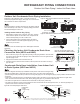
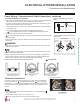
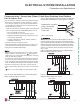
2XWGRRU8QLW&RQGHQVDWH'UDLQ3LSLQJ,QVWDOODWLRQ
Figure 55: HEV2 Outdoor Unit Drain Connection Components
Figure 56: HXV2 Outdoor Unit Drain Connection Components
'UDLQ:DVKHU
/68+(9/68+(9
'UDLQ&DS
'UDLQ&RQQHFWLRQ
'UDLQ&RQQHFWLRQ
'UDLQ:DVKHU
'UDLQ&DS
/68+(9/68+(9
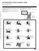
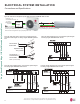
&RQGHQVDWH'UDLQ+RVH,QVWDOODWLRQIURP,QGRRU8QLW
WR'UDLQ6\VWHP+(9DQG+;9
Refer to the diagrams and follow proper installation and the position of the drain hose along the refrig-
erant piping installation path to avoid leaks. After the drain hose is set in place, always follow with leak
/ pressure testing and deep evacuation procedures of the refrigerant piping to be sure all refrigerant piping is properly installed. Re-check and retest
as necessary.
• Drain hose is routed from the indoor unit through the structure (wall) to the outdoor. It must slope at an angle where it is higher at the
indoor unit and lower toward the outdoor area, thereby letting gravity push any condensation down and out.
• The drain hose might need to be extended so that condensate can be properly routed away.
• The drain hose extension must be properly insulated to ensure condensation will not damage walls, floors, etc. Foamed polyethylene or
equivalent of at least 5/16 inches thick is required.
Downward Slope
to Outdoor
for Proper Drainage
Indoor
Unit
Piping
Indoor Outdoor
Indoor Unit
Drain Hose
Indoor Unit
Drain Hose
Insulation
(>4 to 12 inches long
and 5/16 inches thick)
Drain Hose
Extension
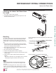
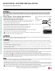
&KRRVLQJWKH,QGRRU8QLW&RQGHQVDWH'UDLQ+RVH
&RQQHFWLRQ6LGH+(9DQG+;9
1. Remove the drain plug on left or right side depending on the piping installation. Insert the drain
hose on the left side when left side piping is used; install the drain hose on the right side when
right side piping is used.
2. Plug up the unused drain hose hole with a drain cap.
3. Install the drain hose onto the drain connection, and firmly attach it to the indoor unit using a
type “E” screw.
Figure 57: Choosing the Location of the
Drain Hose Connection (HEV2 and HXV2).
Figure 58: Installing the Drain Hose.
Figure 59: Correct Slope Angle for Drain Hose. Figure 60: Indoor Unit Drain Hose Extension.
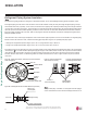
2XWGRRU8QLW'UDLQ3LSLQJ,QGRRU8QLW'UDLQ+RVH
'UDLQ&DS
'UDLQ:DVKHU
'UDLQ&RQQHFWLRQ
/68+;9/68+;9