
Mega 115V Installation Manual

5HIULJHUDQW3LSLQJ&RQQHFWLRQV
Due to our policy of continuous product innovation, some specifications may change without notification.
©LG Electronics U.S.A., Inc., Englewood Cliffs, NJ. All rights reserved. “LG” is a registered trademark of LG Corp.
5()5,*(5$173,3,1*&211(&7,216
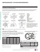
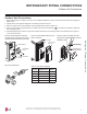
Pipe Size
(in. O.D.)
Outside
Diameter (mm)
Torque
(ft-lbs.)
1/4 6.35 13.0 - 18.0
3/8 9.52 24.6 - 30.4
1/2 12.7 39.8 - 47.7
5/8 15.88 45.4 - 59.3
3/4 19.05 71.5 - 87.5
Table 18: Torque Wrench Tightening.
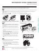
2XWGRRU8QLW&RQQHFWLRQV
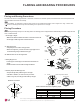
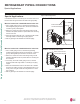
1. Remove the piping cover or piping / control box cover (configuration depends on outdoor unit model) from the unit by loosening the fas-
tening screws.
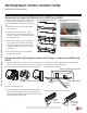
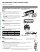
2. Align the center of the refrigerant piping and corresponding connection as shown.
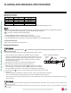
3. Refer to the figures below for liquid and gas (vapor) piping attachments onto the outdoor unit.
4. Place a couple of drops of PVE refrigerant oil on outside of the flare before assembling.
Do not add any contaminants. Tighten the
flare nut initially by hand.
5. Finish tightening the flare nut with a torque wrench until the wrench clicks. Follow torque guidelines in the table below. See figures for
correct connection points.
7HUPLQDO%ORFN
3LSLQJ&RQWURO
%R[&RYHU
3LSLQJ&RQQHFWLRQ
&RYHU
&RQWURO%R[
&RYHU
7HUPLQDO%ORFN
2XWGRRU8QLW
7RUTXH:UHQFK
/LTXLG6LGH3LSLQJ
6PDOOHU'LDPHWHU
9DSRU6LGH3LSLQJ
/DUJHU'LDPHWHU
Figure 40: LSU090-120HEV2 and LSU090-
120HXV2 Piping / Control Box Cover Removal
(Appearances Will Differ Depending on Model).
Figure 41: LSU180-240HEV2 Piping / Control
Box Cover Removal.
Figure 42: Outdoor Unit Piping Connection
(Appearances Will Differ Depending on Model).
Figure 43: Pipe Attachment.
2XWGRRU8QLW&RQQHFWLRQV