6,1*/( =21( 0(*$ $1' 0(*$ 9 :$// 02817(' ,167$//$7,21 0$18$/ 6LQJOH =RQH 0HJD /6 +(9 /6 +(9 /6 +(9 /6 +(9 6LQJOH =RQH 0HJD 9 /6 +;9 /6 +;9
35235,(7$5< '$7$ 127,&( This document, as well as all reports, illustrations, data, information, and other materials are the property of LG Electronics U.S.A., Inc., and are disclosed by LG Electronics U.S.A., Inc., only in confidence. This document is for design purposes only. 'R QRW WKURZ DZD\ GHVWUR\ RU ORVH WKLV PDQXDO Please read carefully and store in a safe place for future reference. Content familiarity required for proper installation.
6$)(7< ,16758&7,216 The instructions below must be followed to prevent product malfunction, property damage, injury or death to the user or other people. Incorrect operation due to ignoring any instructions will cause harm or damage. The level of seriousness is classified by the symbols described below. 7$%/( 2) 6<0%2/6 DANGER This symbol indicates an imminently hazardous situation which, if not avoided, will result in death or serious injury.
6$)(7< ,16758&7,216 6LQJOH =RQH 0HJD DQG 0HJD 9 :DOO 0RXQWHG ,QVWDOODWLRQ 0DQXDO ,167$//$7,21 &217,18(' ,I WKH DLU FRQGLWLRQHU LV LQVWDOOHG LQ D VPDOO VSDFH WDNH PHDVXUHV WR SUHYHQW WKH UHIULJHUDQW FRQFHQWUDWLRQ IURP H[FHHGLQJ VDIHW\ OLPLWV LQ WKH HYHQW RI D UHIULJHUDQW OHDN Consult the latest edition of ASHRAE (American Society of Heating, Refrigerating, and Air Conditioning Engineers) Standard 15.
6$)(7< ,16758&7,216 :,5,1* +LJK YROWDJH HOHFWULFLW\ LV UHTXLUHG WR RSHUDWH WKLV V\VWHP $GKHUH WR WKH 1DWLRQDO (OHFWULFDO &RGHV DQG WKHVH LQVWUXFWLRQV ZKHQ ZLULQJ Improper connections and inadequate grounding can cause accidental injury or death. 7XUQ WKH SRZHU Rႇ DW WKH QHDUHVW GLVFRQQHFW EHIRUH VHUYLFLQJ WKH HTXLSPHQW Electrical shock can cause physical injury or death. 3URSHUO\ VL]H DOO FLUFXLW EUHDNHUV RU IXVHV 7KHUH LV ULVN RI ¿UH HOHFWULF VKRFN H[SORVLRQ SK\VLFDO LQMXU\ RU GHDWK $OZD
$)(7< ,16758&7,216 23(5$7,21 3HULRGLFDOO\ YHULI\ WKDW WKH KDUGZDUH VHFXULQJ WKH XQLW KDV QRW GHWHULRUDWHG 6LQJOH =RQH 0HJD DQG 0HJD 9 :DOO 0RXQWHG ,QVWDOODWLRQ 0DQXDO 'R QRW SURYLGH SRZHU WR RU RSHUDWH WKH XQLW LI LW LV ÀRRG HG RU VXEPHUJHG If the unit falls from its installed location, it can cause property damage, product failure, physical injury or death. 7KHUH LV ULVN RI ¿UH HOHFWULF VKRFN SK\VLFDO LQMXU\ RU GHDWK ,I JDV OHDNV RXW YHQWLODWH WKH DUHD EHIRUH RSHUDWLQJ WKH XQLW 8VH D GHG
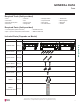
$%/( 2) &217(176 Safety Instructions ............................................................................. 3-6 General Data ..................................................................................... 8-12 Unit Nomenclature ............................................................................... 8 Parts .................................................................................................... 9 6SHFL¿FDWLRQV ................................................................
*(1(5$/ '$7$ 8QLW 1RPHQFODWXUH 6LQJOH =RQH :DOO 0RXQW ,QGRRU DQG 2XWGRRU 8QLWV 6LQJOH =RQH 0HJD DQG 0HJD 9 :DOO 0RXQWHG ,QVWDOODWLRQ 0DQXDO /6 1 +(9 Family LA= Art Cool Premier / Gallery / Mirror LS= High Efficiency Wall Mount / Standard / Mega Type N = Indoor Wall Mount Unit U = Outdoor Heat Pump Unit No N or U = System Nominal Capacity (Nominal cooling capacity in Btu/h) 090 = 9,000 120 = 12,000 180 = 18,000 240 = 24,000 300/307 = 30,000 360 = 36,000 Indoor/Outdoor Product HEV = Mega HXV = M
*(1(5$/ '$7$ 3DUWV 5HTXLUHG 7RROV ILHOG SURYLGHG • • • • Level Screwdriver Electrical lineman pliers Electric drill • • • • • • • • Hole saw Drill Flaring tool set Tubing cutter Tube/pipe reamer Torque wrenches Allen wrench Gas-leak detector • • • • Thermometer Measuring tape Multimeter Ammeter 5HTXLUHG 3DUWV ILHOG SURYLGHG • Connecting cable (power and control) • Pipes - vapor line and liquid line, with insulation • Insulated drain hose • Additional drain hose ,QFOXGHG 3DUWV 'HSHQGV RQ 0RGHO
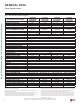
*(1(5$/ '$7$ 0HJD 6SHFL¿FDWLRQV Table 1: Single =one Mega System Speci¿cations. LS090HEV2 LS120HEV2 LS180HEV2 LS240HEV2 (LSN090HEV2/ (LSN120HEV2/ (LSN180HEV2/ (LSN240HEV2/ LSU090HEV2) LSU120HEV2) LSU180HEV2) LSU240HEV2) Cooling Capacity (Min/Rated/Max) (Btu/h) 3,070 ~ 9,000 ~10,330 3,070 ~ 12,000 ~ 13,780 3,685 ~ 18,000 ~ 18,493 3,685 ~ 22,000 ~ 24,000 Cooling Power Input1 (kW) 0.72 1.142 1.5 2.
*(1(5$/ '$7$ 0HJD 9 6SHFL¿FDWLRQV Table 2: Single =one Mega 115V System Speci¿cations. LS090HXV2 (LSN090HXV2/LSU090HXV2) LS120HXV2 (LSN120HXV2/LSU120HXV2) 3,070 ~ 9,000 ~ 10,330 3,070 ~ 12,000 ~ 13,780 0.732 1.142 3,070 ~ 10,900 ~ 12,520 3,070 ~ 12,000 ~ 13,780 0.875 1.000 3.65 3.52 12.30 10.51 20 19 10 9.5 115/60/1 14 to 118 14 to 65 53 to 75 60 to 86 65 to 86 60 to 86 42 / 36 / 28 / 21 50 19.2 / 22 58.4 / 60 R410A EEV 42 / 36 / 28 / 21 50 19.2 / 22 58.
*(1(5$/ '$7$ (OHFWULFDO Table 3: 208-230V, 60Hz, 1-Phase Single-Zone Mega System Electrical Data Table. 6LQJOH =RQH 0HJD DQG 0HJD 9 :DOO 0RXQWHG ,QVWDOODWLRQ 0DQXDO Voltage Nominal Unit Model Hertz Voltage Range (Min. Tons No. to Max.) 3/4 LS090HEV2 1 LS120HEV2 1-1/2 LS180HEV2 2 LS240HEV2 60 208 - 230 187 - 253 Compressor Motor RLA Cooling Heating MCA MOP 10.0 15 1 7.0 7.0 43 10.0 15 1 7.0 7.0 15.0 20 1 10.0 15.0 20 1 10.0 W FLA 0.4 30 0.4 43 0.4 30 0.4 10.
*(1(5$/ ,167$//$7,21 *8,'(/,1(6 2XWGRRU 8QLW /RFDWLRQ 6HOHFWLRQ 6HOHFWLQJ WKH %HVW /RFDWLRQ IRU WKH 2XWGRRU 8QLW DANGER • Do not install the unit in an area where combustible gas will generate, flow, stagnate, or leak. These conditions can cause a fire, resulting in bodily injury or death. • Do not install the unit in a location where acidic solution and spray (sulfur) are often used as it can cause bodily injury or death.
*(1(5$/ ,167$//$7,21 *8,'(/,1(6 2XWGRRU 8QLW /RFDWLRQ 6HOHFWLRQ Planning for Snow and Ice, continued. 6LQJOH =RQH 0HJD DQG 0HJD 9 :DOO 0RXQWHG ,QVWDOODWLRQ 0DQXDO When deciding on a location to place the outdoor unit, be sure to choose an area where run-off water from defrost cycle will not accumulate and freeze on sidewalks or driveways, which will create unsafe conditions.
*(1(5$/ ,167$//$7,21 *8,'(/,1(6 2XWGRRU 8QLW /RFDWLRQ 6HOHFWLRQ 2FHDQVLGH $SSOLFDWLRQV Figure 2: Oceanside Placement Using Windbreak. Use of a Windbreak to Shield from Sea Wind Windbreak Ocean winds will cause corrosion, particularly on the condenser and HYDSRUDWRU ¿QV ZKLFK LQ WXUQ FRXOG FDXVH SURGXFW PDOIXQFWLRQ RU LQHI¿FLHQW SHUIRUPDQFH • • • • Additional anti-corrosion treatment will need to be applied to the outdoor unit at oceanside locations.
*(1(5$/ ,167$//$7,21 *8,'(/,1(6 5HTXLUHG 2XWGRRU 8QLW &OHDUDQFHV 6LQJOH =RQH 0HJD DQG 0HJD 9 :DOO 0RXQWHG ,QVWDOODWLRQ 0DQXDO 0LQLPXP $OORZDEOH &OHDUDQFH DQG 6HUYLFH $FFHVV 5HTXLUHPHQWV Proper clearance for the outdoor unit coil is critical for proper operation. When installing the outdoor unit, consider service, inlet and outlet, and minimum allowable space requirements as illustrated in the diagrams below. • Include enough space for airflow and for service access.
*(1(5$/ ,167$//$7,21 *8,'(/,1(6 5LJJLQJ DQG /LIWLQJ 2XWGRRU 8QLW 0RXQWLQJ 5LJJLQJ DQG /LIWLQJ ,QVWUXFWLRQV :HDU SURWHFWLYH JORYHV DQG VDIHW\ JRJJOHV ZKHQ KDQGOLQJ HTXLSPHQW 6KDUS HGJHV ZLOO FDXVH SHUVRQDO LQMXU\ 'LVSRVH RI WKH SDFNLQJ PDWHULDOV VDIHO\ • Packing materials, such as nails and other metal or wooden parts, will cause puncture wounds or other injuries. • Tear apart and throw away plastic packaging bags so that children do not play with them and risk suffocation and death.
*(1(5$/ ,167$//$7,21 *8,'(/,1(6 2XWGRRU 8QLW 0RXQWLQJ Concrete Platform Specifications Figure 6: Example of Using an Insert for a Hole in a Reinforced Concrete Beam. Figure 7: Close up of Bolt Attachment. $QFKRU %ROW 0 0LQ LQFKHV 0LQ WR LQFKHV Polyblock / Anti-Vibration Material Insert 6LQJOH =RQH 0HJD DQG 0HJD 9 :DOO 0RXQWHG ,QVWDOODWLRQ 0DQXDO • Concrete foundations must be made of one part cement, two parts sand, and four parts gravel.
*(1(5$/ ,167$//$7,21 *8,'(/,1(6 ,QGRRU 8QLW /RFDWLRQ 6HOHFWLRQ 5HTXLUHG ,QGRRU 8QLW &OHDUDQFHV 6HOHFWLQJ WKH %HVW /RFDWLRQ IRU WKH ,QGRRU 8QLW Follow recommended best practices when choosing an indoor location for the single zone indoor unit. Figure 10: Mega Indoor Unit Clearance Requirements. 8QLW ,QFK PP Dos ! ! ! $W OHDVW IHHW IURP WKH IORRU Table 8: Mega Indoor Unit Ceiling Clearance.
*(1(5$/ ,167$//$7,21 *8,'(/,1(6 ,QGRRU 8QLW 0RXQWLQJ Figure 12: Drilling Piping Hole. WALL Follow all piping clearance recommendations. 1. Using a 2-9/16 inch hole core drill bit, drill a hole at either the right or left side of the wall mounting, pre-chosen following installation guidelines and application needs. • The slant of the hole must be 3/16” to 5/16 inches from level with the slant being upward on the indoor unit side and downward on the outdoor unit side. 2.
*(1(5$/ ,167$//$7,21 *8,'(/,1(6 ,QGRRU 8QLW 0RXQWLQJ ,QVWDOODWLRQ 3ODWH &KDVVLV +RRN 8QLW 2XWOLQH 7\SH $ 6FUHZV ,QVWDOODWLRQ 3ODWH Figure 18: Mega 18 and 24K Wall Mount Indoor Unit Installation Plate Dimensions.
*(1(5$/ ,167$//$7,21 *8,'(/,1(6 ,QGRRU 8QLW 0RXQWLQJ Removing the Indoor Unit Bottom Cover (Mega HEV2 and Mega 115V HXV2 Indoor Units), continued. 6LQJOH =RQH 0HJD DQG 0HJD 9 :DOO 0RXQWHG ,QVWDOODWLRQ 0DQXDO Figure 23: Bottom Cover with Top and Middle Unsnapped, Front View (Appearances Will Vary Depending on Indoor Unit Model). Figure 22: Back of Bottom Cover Completely Removed from Indoor Unit (Appearances Will Vary Depending on Indoor Unit Model).
*(1(5$/ ,167$//$7,21 *8,'(/,1(6 ,QGRRU 8QLW 0RXQWLQJ 0RXQWLQJ WKH ,QGRRU 8QLW WR WKH ,QVWDOODWLRQ 3ODWH 1. Position the indoor unit onto the upper portion of the installation plate. Figure 25: Attaching the Indoor Unit to the Installation Plate (Mega Example. Appearances Will Vary Depending on Model). 2. Engage the hooks at the top of the indoor unit with the upper edge of the installation plate (number of hooks depends on model type). 3.
*(1(5$/ ,167$//$7,21 *8,'(/,1(6 ,QGRRU 8QLW 0RXQWLQJ 6LQJOH =RQH 0HJD DQG 0HJD 9 :DOO 0RXQWHG ,QVWDOODWLRQ 0DQXDO 3UHSDULQJ IRU 3LSLQJ (OHFWULFDO &RQQHFWLRQV 1. To prepare the indoor unit for piping and electrical installation, disengage bottom on indoor unit from installation plate by reversing Steps 6, 5, and 4 from the previous procedure, if those procedures have been performed. 2. Unsnap the piping / drain hose holder (L-bracket) out from the indoor unit chassis.
5()5,*(5$17 6$)(7< 67$1'$5'6 '(9,&( &211(&7,21 /,0,7$7,216 5HIULJHUDQW 6DIHW\ 6WDQGDUGV ASHRAE Standards 15-2010 and 34-2010 address refrigerant safety and the maximum allowable concentration of refrigerant in an occupied space. Refrigerant will dissipate into the atmosphere, but a certain volume of air is required to safely dissipate the refrigerant. For R410A refrigerant, the maximum allowable concentration of refrigerant is 26 lbs.
6(/(&7,1* ),(/' 6833/,(' 3,3,1* 6HOHFWLQJ )LHOG 6XSSOLHG &RSSHU 3LSLQJ 6LQJOH =RQH 0HJD DQG 0HJD 9 :DOO 0RXQWHG ,QVWDOODWLRQ 0DQXDO Always follow local codes when selecting and installing copper pipe and piping system components. Approved piping for use with LG Single Zone products will be marked “R410 RATED” along the length of the pipe. Piping wall thickness must meet local code requirements and be approved for a maximum operating pressure of 551 psi.
&233(5 (;3$16,21 $1' &2175$&7,21 &RSSHU ([SDQVLRQ DQG &RQWUDFWLRQ Under normal operating conditions, the vapor pipe temperature of a Duct Free System can vary as much as 280°F. With this large variance in pipe temperature, the designer must consider pipe expansion and contraction to avoid pipe and fitting fatigue failures. If the pipe is mounted in free air space, no natural restriction to movement is present if mounting clamps are properly spaced and installed.
&233(5 (;3$16,21 $1' &2175$&7,21 6LQJOH =RQH 0HJD DQG 0HJD 9 :DOO 0RXQWHG ,QVWDOODWLRQ 0DQXDO Table 13: Linear Thermal Expansion of Copper Tubing in Inches. Pipe Length1 10 20 30 40 50 60 70 80 90 100 120 140 160 180 1 35° 0.04 0.08 0.12 0.16 0.20 0.24 0.28 0.32 0.36 0.40 0.48 0.56 0.64 0.72 40° 0.04 0.08 0.12 0.16 0.20 0.24 0.28 0.32 0.36 0.40 0.48 0.56 0.64 0.72 45° 0.05 0.10 0.15 0.20 0.25 0.30 0.35 0.40 0.45 0.50 0.60 0.70 0.80 0.90 50° 0.06 0.12 0.18 0.24 0.30 0.36 0.42 0.48 0.54 0.60 0.72 0.
3,3,1* 0$7(5,$/6 $1' +$1'/,1* 3LSLQJ 0DWHULDOV DQG +DQGOLQJ Keep Pipes Capped While Storing. Pipes used for the refrigerant piping system must include the specified thickness, and the interior must be clean. While handling and storing, do not bend or damage the pipes, and take care not to contaminate the interior with dust, moisture, etc. Keep refrigerant pipe dry, clean, and airtight. Moisture Possible - Significant hydrolysis of refrigerant oil. Problems - Refrigerant oil degradation.
5()5,*(5$17 6<67(0 (1*,1((5,1* 6LQJOH =RQH 0HJD DQG 0HJD 9 :DOO 0RXQWHG ,QVWDOODWLRQ 0DQXDO Proper system operation depends on the installer using utmost care while assembling the piping system. The following pages are an overview of best practices when installing the refrigerant piping system. LG Electronics U.S.A.,Inc.
5()5,*(5$17 6<67(0 (1*,1((5,1* 2EVWDFOHV Figure 32: Installing Piping Above and Below an Obstacle. 3X MINIMUM X X 3X MINIMUM Above an obstacle Below an obstacle 3LSH 6XSSRUWV Figure 33: Pipe Hanger Details. A properly installed pipe system must be adequately supported to avoid pipe sagging. Sagging pipes become oil traps that lead to equipment malfunction. Pipe supports must never touch the pipe wall; supports must be installed outside (around) the primary pipe insulation jacket.
5()5,*(5$17 6<67(0 (1*,1((5,1* 3LSH 6OHHYHV DW 3HQHWUDWLRQV 6LQJOH =RQH 0HJD DQG 0HJD 9 :DOO 0RXQWHG ,QVWDOODWLRQ 0DQXDO LG recommends that all pipe penetrations through walls, floors, and pipes buried underground be properly insulated and routed through an appropriate wall sleeve of sufficient size to prevent compression of refrigerant pipe insulation and free movement of the pipe within the sleeve.
)/$5,1* $1' %5$=,1* 352&('85(6 )ODULQJ DQG %UD]LQJ 3URFHGXUHV One of the main causes of refrigerant leaks is a defective connection. For LG HVAC systems, the installer needs to know how perform both flared and brazed connections successfully. • During installation, it is imperative to keep the piping system free of contaminants and debris such as copper burrs, slag, or carbon dust. Do not use kinked pipe caused by excessive bending in one specific area on its length. • )ODULQJ 3URFHGXUH 1.
)/$5,1* $1' %5$=,1* 352&('85(6 6LQJOH =RQH 0HJD DQG 0HJD 9 :DOO 0RXQWHG ,QVWDOODWLRQ 0DQXDO Tightening the Flare Nuts Tightening Torque for Flare Nuts. Pipe Size (in. O.D.) Outside Diameter (mm) Tightening Torque (ft-lbs.) 13.0 - 18.0 1/4 6.35 9.52 24.6 - 30.4 3/8 39.8 - 47.7 1/2 12.7 45.4 - 59.3 15.88 5/8 71.5 - 87.5 19.05 3/4 1. When connecting the flare nuts, coat the flare (outside only) with polyvinyl ether (PVE) refrigeration oil only.
5()5,*(5$17 3,3,1* &211(&7,216 ,QVWDOODWLRQ 2YHUYLHZ ,QVWDOODWLRQ Single Zone Mega and Mega 115V Wall-Mounted systems are one-to-one systems. There is a direct piping connection between the outdoor unit and the indoor unit. The figure at right illustrates the basic pipe connections between the outdoor and indoor unit. Refer to the illustration when proceeding with pipe connections. The illustration shows the indoor unit being installed at a higher position than the outdoor unit.
5()5,*(5$17 3,3,1* &211(&7,216 6SHFLDO $SSOLFDWLRQV 6SHFLDO $SSOLFDWLRQV Figure 39: Special Applications. 6LQJOH =RQH 0HJD DQG 0HJD 9 :DOO 0RXQWHG ,QVWDOODWLRQ 0DQXDO If an additional drain hose is necessary, the end of drain outlet must be routed above the ground. Secure the drain hose appropriately. When the Outdoor Unit is Installed Below the Indoor Unit: 1.
5()5,*(5$17 3,3,1* &211(&7,216 2XWGRRU 8QLW &RQQHFWLRQV 2XWGRRU 8QLW &RQQHFWLRQV 1. Remove the piping cover or piping / control box cover (configuration depends on outdoor unit model) from the unit by loosening the fastening screws. 2. Align the center of the refrigerant piping and corresponding connection as shown. 3. Refer to the figures below for liquid and gas (vapor) piping attachments onto the outdoor unit. 4. Place a couple of drops of PVE refrigerant oil on outside of the flare before assembling.
5()5,*(5$17 3,3,1* &211(&7,216 ,QGRRU 8QLW &RQQHFWLRQV 6LQJOH =RQH 0HJD DQG 0HJD 9 :DOO 0RXQWHG ,QVWDOODWLRQ 0DQXDO 5HPRYLQJ WKH ,QGRRU 8QLW %RWWRP &RYHU +(9 DQG +;9 To access the indoor unit piping port connections, and to make the indoor unit installation procedure easier, it is recommended that the bottom cover be removed first. 1. Unsnap the bottom cover at its top left and right sides (Location 1). Figure 44: Removing the Bottom Cover. Figure 45: Removing the Bottom Cover, Alternate View. 2.
5()5,*(5$17 3,3,1* &211(&7,216 ,QGRRU 8QLW &RQQHFWLRQV Accessing and Positioning the Indoor Unit Piping / Connections (HEV2 and HXV2), continued. • Do not bend the piping directly backwards or to the left or right sides without bending it downward first; this will damage the indoor unit piping. • Do not forcibly press the refrigerant piping onto the bottom frame or the front grille; this will damage the indoor unit piping and / or indoor unit frame. • Ensure the piping is straight.
5()5,*(5$17 3,3,1* &211(&7,216 ,QGRRU 8QLW &RQQHFWLRQV 6LQJOH =RQH 0HJD DQG 0HJD 9 :DOO 0RXQWHG ,QVWDOODWLRQ 0DQXDO Accessing and Positioning the Indoor Unit Piping / Connections (HEV2 and HXV2), continued. Figure 52: Piping Installation When Piping is on the Right Side.
5()5,*(5$17 3,3,1* &211(&7,216 2XWGRRU 8QLW 'UDLQ 3LSLQJ ,QGRRU 8QLW 'UDLQ +RVH 2XWGRRU 8QLW &RQGHQVDWH 'UDLQ 3LSLQJ ,QVWDOODWLRQ Depending on the installation location, it could be necessary to install factory-supplied drain plug(s). See pages 13 to 16 for information in reference to outdoor unit placement. Figure 55: HEV2 Outdoor Unit Drain Connection Components 'UDLQ &DS 'UDLQ :DVKHU Ensure drain piping is insulated.
5()5,*(5$17 3,3,1* &211(&7,216 ,QGRRU 8QLW 'UDLQ +RVH 6LQJOH =RQH 0HJD DQG 0HJD 9 :DOO 0RXQWHG ,QVWDOODWLRQ 0DQXDO Condensate Drain Hose Installation; from Indoor Unit to Drain System (HEV2 and HXV2), continued. • Insert the drain hose >two (2) inches so it won’t pull out of the field-supplied drain pipe. Avoid piping the drain hose as shown in the diagrams in the • figure below. These methods are incorrect and can cause leaks at the indoor unit site.
5()5,*(5$17 3,3,1* &211(&7,216 ,QGRRU 8QLW 'UDLQ +RVH &KHFNLQJ WKH ,QGRRU 8QLW 'UDLQ +RVH IRU /HDNV Figure 65: Checking for Leaks at the Indoor Unit. 1. Pour a glass of water on the evaporator. 2. Verify that the water flows appropriately through and out of the drain hose without any leaks.
,168/$7,21 5HIULJHUDQW 3LSLQJ 6\VWHP ,QVXODWLRQ 6LQJOH =RQH 0HJD DQG 0HJD 9 :DOO 0RXQWHG ,QVWDOODWLRQ 0DQXDO )RU LQIRUPDWLRQ UHJDUGLQJ LQVXODWLRQ IRU XQGHUJURXQG RU SHQHWUDWLRQ VLWXDWLRQV VHH WKH ³*HQHUDO 5HIULJHUDQW 3LSLQJ 6\VWHP ,QIRUPDWLRQ´ VHFWLRQ All refrigerant piping from the outdoor unit to the indoor units must be insulated correctly for safety and usage.
,168/$7,21 Minimum Refrigerant Pipe Ethylene Propylene Diene Methylene (EPDM) Insulation Wall Thickness Requirements • Do not insulate gas and liquid pipes together as this can result in pipe leakage and malfunction due to extreme temperature fluctuations. • Always properly insulate the piping. Insufficient insulation will result in condensation, reduced heating/cooling performance, etc. Also, if the pipes aren’t insulated properly, condensation could potentially cause damage to building finishes.
(/(&75,&$/ 6<67(0 ,167$//$7,21 6DIHW\ *XLGHOLQHV &RQQHFWLRQV DQG 6SHFL¿FDWLRQV 6LQJOH =RQH 0HJD DQG 0HJD 9 :DOO 0RXQWHG ,QVWDOODWLRQ 0DQXDO 0HJD /6 +(9 DQG 0HJD 9 /6 +;9 LQGRRU XQLWV DQG RXWGRRU XQLWV KDYH VLPLODU IUDPHV KRZHYHU 0HJD /6 +(9 V\VWHPV UHTXLUH 9 +] SK SRZHU VXSSO\ ZKLOH /6 +;9 V\VWHPV UHTXLUH 9 +] SK SRZHU VXSSO\ 9HULI\ ZKLFK V\VWHP LV EHLQJ LQVWDOOHG $Q LQFRUUHFW SRZHU VXSSO\ ZLOO UHVXOW LQ HOHFWULF VKRFN ¿UH SK\VLFDO LQMXU\
(/(&75,&$/ 6<67(0 ,167$//$7,21 &RQQHFWLRQV DQG 6SHFL¿FDWLRQV 3RZHU :LULQJ &RPPXQLFDWLRQ &DEOH &RQQHFWLRQV FRQWLQXHG WARNING Figure 72: Adding a Ring Terminal to the Wiring. Ring Terminal Figure 73: Tightening the Ring Terminal to the Terminal Plate. (OHFWULFDO 6\VWHP ,QVWDOODWLRQ 1. Remove the JIS terminal screws from the (outdoor unit or indoor unit) terminal plate with a JIS screwdriver. (See information about LG terminal connections below.) 2.
(/(&75,&$/ 6<67(0 ,167$//$7,21 &RQQHFWLRQV DQG 6SHFL¿FDWLRQV 6LQJOH =RQH 0HJD DQG 0HJD 9 :DOO 0RXQWHG ,QVWDOODWLRQ 0DQXDO 0HJD /6 +(9 DQG 0HJD 9 /6 +;9 LQGRRU XQLWV DQG RXWGRRU XQLWV KDYH VLPLODU IUDPHV KRZHYHU 0HJD /6 +(9 V\VWHPV UHTXLUH 9 +] SK SRZHU VXSSO\ ZKLOH /6 +;9 V\VWHPV UHTXLUH 9 +] SK SRZHU VXSSO\ 9HULI\ ZKLFK V\VWHP LV EHLQJ LQVWDOOHG $Q LQFRUUHFW SRZHU VXSSO\ ZLOO UHVXOW LQ HOHFWULF VKRFN ¿UH SK\VLFDO LQMXU\ RU GHDWK 3RZHU 6XS
(/(&75,&$/ 6<67(0 ,167$//$7,21 &RQQHFWLRQV DQG 6SHFL¿FDWLRQV &RPPXQLFDWLRQ &RQQHFWLRQ 3RZHU &DEOH 6SHFLILFDWLRQV IURP 2XWGRRU Figure 78: Typical Single Zone Outdoor Unit to Indoor Unit Wiring and 8QLW WR ,QGRRU 8QLW • Always verify the communication cable is connected to a communications terminal on the Single Zone unit. Never apply line voltage power to the communication cable connection. If contact is made, the PCBs will be damaged.
(/(&75,&$/ 6<67(0 ,167$//$7,21 &RQQHFWLRQV DQG 6SHFL¿FDWLRQV Figure 82: Schematic of a Single Zone System When the Wiring is GREATER THAN 130 Feet.
(/(&75,&$/ 6<67(0 ,167$//$7,21 &RQWUROOHU 2SWLRQV &RQWUROOHU 2SWLRQV Single Zone Mega and Mega 115V Wall Mount systems include a wireless handheld remote controller (Model No. AKB74955602). Optional LG-suppled wired controllers are available for the Mega 115V units. See “Functions, Controls, Options” in the Single Zone Mega (HEV2) and Mega 115V (HXV2) Wall Mounted Engineering Manual”, or contact an LG representative for more information.
(/(&75,&$/ 6<67(0 ,167$//$7,21 ,QGRRU 8QLW (OHFWULFDO &RQQHFWLRQV 6LQJOH =RQH 0HJD DQG 0HJD 9 :DOO 0RXQWHG ,QVWDOODWLRQ 0DQXDO &RQQHFWLQJ ,QGRRU 8QLW (OHFWULFDO :LULQJ +(9 DQG +;9 • Verify that main power to the unit is completely off before proceeding with these steps as there is a risk of electrical shock, bodily injury, and / or death. • Follow all safety and warning information outlined at the beginning and throughout this manual.
(/(&75,&$/ 6<67(0 ,167$//$7,21 ,QGRRU 8QLW (OHFWULFDO &RQQHFWLRQV Cable Installation When Piping is on the Left Side: • Insert the communication / connection (power) cable through the bottom of the indoor unit, • Connect the terminals to the terminal block. • Secure the cable onto the terminal block with the cable retainer. • Secure the refrigerant piping, drain hose, and communication / connection (power) cable together using cable ties and conduit, or by the bundling method.
(/(&75,&$/ 6<67(0 ,167$//$7,21 2XWGRRU 8QLW (OHFWULFDO &RQQHFWLRQV 6LQJOH =RQH 0HJD DQG 0HJD 9 :DOO 0RXQWHG ,QVWDOODWLRQ 0DQXDO &RQQHFWLQJ 2XWGRRU 8QLW :LULQJ • Verify that main power is completely off and that no power is going through the Single Zone system before proceeding with these steps. Follow all safety and warning information outlined at the beginning of this manual. Failure to do so will cause electric shock, bodily injury and / or death.
(/(&75,&$/ 6<67(0 ,167$//$7,21 2XWGRRU 8QLW (OHFWULFDO &RQQHFWLRQV Connecting Outdoor Unit Wiring, continued. Figure 99: Example of Conduit. Do not install power wiring to the outdoor unit and the communication / connection (power) cable to the indoor unit in the same conduit. Use separate conduits. Communication problems will occur. 6. Using a JIS screwdriver, connect wires as shown at right.
),1$/ ,167$//$7,21 352&('85(6 7ULSOH /HDN 3UHVVXUH 7HVW 6LQJOH =RQH 0HJD DQG 0HJD 9 :DOO 0RXQWHG ,QVWDOODWLRQ 0DQXDO 7ULSOH /HDN 3UHVVXUH 7HVW After the refrigerant piping installation is complete, perform a triple leak / pressure test. Triple leak / pressure test is performed between the outdoor unit and indoor unit to verify that refrigerant can flow through the system without danger of leaks or pressure losses.
),1$/ ,167$//$7,21 352&('85(6 7ULSOH /HDN 3UHVVXUH DQG 'HHS (YDFXDWLRQ 7HVWV Triple Leak / Pressure Check Procedure, continued. 7. If the pressure does NOT drop for one (1) hour, the system passes the test. 8. If the pressure drops, there is a leak and it must be found. Remove the bubble solution with a clean cloth, repair the leak(s), and perform the leak / pressure check again. 9.
),1$/ ,167$//$7,21 352&('85(6 'HHS (YDFXDWLRQ DQG 7ULSOH (YDFXDWLRQ 7HVWV Deep Evacuation Procedure, continued. Figure 104: Evacuation Procedure Diagram. ,QGRRU 8QLW 6LQJOH =RQH 0HJD DQG 0HJD 9 :DOO 0RXQWHG ,QVWDOODWLRQ 0DQXDO 3. Evacuate to static micron level 500 for at least one (1) hour. 4. Micron level must remain 500 for two (2) hours. If the vacuum gauge rises and stops, the system may contain moisture; therefore, it will be necessary to repeat the steps of vacuum break and drying.
),1$/ ,167$//$7,21 352&('85(6 7ULSOH (YDFXDWLRQ 7HVW Triple Evacuation Procedure Steps 1. If this procedure is performed shortly after the leak / pressure test, the cap and core on the gas (vapor) suction Schrader port must have already been removed, and the manifold must already be connected. If the procedure was not performed shortly after the leak / pressure test, make sure to remove the cap and core on the gas (vapor) suction Schrader port.
),1$/ ,167$//$7,21 352&('85(6 5HIULJHUDQW 7ULP &KDUJH )LQLVKLQJ WKH -RE 6LQJOH =RQH 0HJD DQG 0HJD 9 :DOO 0RXQWHG ,QVWDOODWLRQ 0DQXDO 5HIULJHUDQW 7ULP &KDUJH The single zone system will need an additional refrigerant charge if the installed piping lengths are greater than the “piping length (no additional refrigerant, ft.) specification” listed in the product tables. See the product sections in the engineering and installation manuals.
),1$/ ,167$//$7,21 352&('85(6 5HDWWDFKLQJ WKH ,QGRRU 8QLW %RWWRP &RYHU 5HDWWDFKLQJ WKH ,QGRRU 8QLW %RWWRP &RYHU +(9 DQG +;9 Reattach the indoor unit bottom cover after all other installation procedures are complete. Figure 105: Close Up of Bottom Cover Connections (Appearances Will Vary Depending on Indoor Unit Model). Top Snaps 1. If ON, shut power OFF to the system. C-Hooks 2.
),1$/ ,167$//$7,21 352&('85(6 $LU )LOWHU 'LVDVVHPEO\ DQG $VVHPEO\ $LU )LOWHU 'LVDVVHPEO\ DQG $VVHPEO\ +(9 DQG +;9 Air Filter Disassembly Figure 110: Disassembling the Air Filter (Appearances Will Vary Depending on Indoor Unit Model). 2. Lifting the Air Filter by the Handles. 6LQJOH =RQH 0HJD DQG 0HJD 9 :DOO 0RXQWHG ,QVWDOODWLRQ 0DQXDO 1. Turn power off to the system. 2. Find the handles located at the top-front of the air filter molded into the plastic frame support. 3.
),1$/ ,167$//$7,21 352&('85(6 ,QVWDOOLQJ %DWWHULHV 7HVW 5XQ 3HUIRUPDQFH (YDOXDWLRQ ,QVWDOOLQJ %DWWHULHV LQWR WKH +DQGKHOG 5HPRWH &RQWUROOHU Figure 112: Installing the Remote Controller Batteries. For information on using the handheld remote controller, refer to its owner’s manual. 1. The remote controller needs two AAA (1.5V) batteries for operation. Remove the battery cover from the back of the remote controller by pushing the tab down in the direction seen at right.
),1$/ ,167$//$7,21 352&('85(6 ,QVWDOOHU 0RGH &RROLQJ 2QO\ 0RGH ,QVWDOOHU 0RGH 6LQJOH =RQH 0HJD DQG 0HJD 9 :DOO 0RXQWHG ,QVWDOODWLRQ 0DQXDO It will be necessary to switch to Installer mode if the system needs to operate in Heating Only or Cooling Only modes, or the Pump Down procedure needs to be performed. Figure 115: Using the Handheld Controller to Change System to Installer Mode. To Enter Installer Mode: 1. Press the Reset and “A” buttons.
),1$/ ,167$//$7,21 352&('85(6 3XPS 'RZQ 3URFHGXUH 3XPS 'RZQ 3URFHGXUH This procedure is performed when the refrigerant piping system is serviced. Pumping down collects all the refrigerant in the outdoor unit without losing any charge. Always adhere to and be familiar with local codes regarding the handling of refrigerant. The system must operate in Cooling Only mode to proceed with the pump down procedure. If needed, refer to the previous sections for proper steps to place the unit into Cooling Only mode.
7528%/(6+227,1* 6LQJOH =RQH 0HJD DQG 0HJD 9 :DOO 0RXQWHG ,QVWDOODWLRQ 0DQXDO /* 6,06 6HOI 'LDJQRVLV )XQFWLRQV The SIMs WLAN module and the smart phone app together provide monitoring and troubleshooting capability for LG Duct Free Systems. SIMs function only with LG Duct Free products. LG SIMs can also be used with Single Zone one-to-one configurations such as the Single Zone Wall Mount systems. SIMs app is available for Apple ® iPhone® iOS or Android™ smart phone operating systems.
7528%/(6+227,1* /* 6,06 6HOI 'LDJQRVLV )XQFWLRQV 6,0V $SS 6FUHHQV Outdoor Info/ Component Screen Outdoor Info/ Temperature Screen Displays the following information: • Frequency • FAN1 RPM • FAN2 RPM • DC Link • Current • Voltage • EEV Mode • Restart Timer • Comp Mode • EEV Displays the following information: • Inv TD • Suction • Discharge • Cond Mid • Cond Out • Heatsink • Air Temp Graph Info Tab Displays the following information: • Frequency • Operation • THM Mode • REM Mode • FAN • EEV • Air Te
7528%/(6+227,1* (UURU &RGHV 7URXEOHVKRRWLQJ 8VLQJ (UURU &RGHV 6LQJOH =RQH 0HJD DQG 0HJD 9 :DOO 0RXQWHG ,QVWDOODWLRQ 0DQXDO Refer to the table below and on the next page for error codes that are generated from the indoor and outdoor units. These codes are the most common. Your particular system might generate additional codes not listed here. Please contact LG Support if you see these types of errors and a simple power cycle has not corrected the issue.
7528%/(6+227,1* (UURU &RGHV 0HJD +(9 DQG +;9 6LQJOH =RQH :DOO 0RXQWHG 2XWGRRU 8QLW (UURU &RGHV The Single Zone Wall Mounted outdoor unit error codes are visible on the outdoor unit, as well as from the indoor unit. However, the indoor unit error codes are only visible from the indoor unit and will not display at the outdoor unit. When troubleshooting the system, be sure to verify if the error codes that are being displayed are specific for indoor or outdoor units.
&$87,216 )25 5()5,*(5$17 /($.6 6LQJOH =RQH 0HJD DQG 0HJD 9 :DOO 0RXQWHG ,QVWDOODWLRQ 0DQXDO &DXWLRQV IRU 5HIULJHUDQW /HDNV ,QWURGXFWLRQ ASHRAE Standards 15-2010 and 34-2010 offer guidelines that address refrigerant safety and the maximum allowable concentration of refrigerant in an occupied space. Refrigerant will dissipate into the atmosphere, but a certain volume of air is required for this to occur safely. For R410A refrigerant, the maximum allowable concentration is 0.026 lbs.
Major Component Rough-In Description ,167$//$7,21 &+(&./,67 Single Zone outdoor unit was connected properly per local code and the product installation procedures. All literature and bagged accessories have been removed from the fan discharge. Indoor unit was installed, properly supported, and located indoors in a non-corrosive environment.
20001747 ISO 9001: 2008 LG ELECTRONICS INC. LG Electronics, U.S.A., Inc. Air Conditioning Technologies 4300 North Point Parkway Alpharetta, Georgia 30022 www.lghvac.