SINGLE ZONE MEGA AND MEGA 115V WALL MOUNTED ENGINEERING MANUAL 3/4, 1, 1-1/2, and 2 Tons Mega Models: LS090HEV2 LS120HEV2 LS180HEV2 LS240HEV2 3/4 and 1 Tons Mega 115V Models: LS090HXV2 LS120HXV2
PROPRIETARY DATA NOTICE This document, as well as all reports, illustrations, data, information, and other materials are the property of LG Electronics U.S.A., Inc., and are disclosed by LG Electronics U.S.A., Inc. only in confidence. This document is for design purposes only. A summary list of safety precautions is on page 3 For more technical materials such as submittals, catalogs, installation, owner’s, and service manuals, visit www.lghvac.com. For continual product development, LG Electronics U.S.A.
TABLE OF CONTENTS Unit Nomenclature.......................................................................................................................................................................................................... 4 LG Air Conditioner Technical Solution (LATS) ......................................................................................................................................................... 5-6 Mega and Mega 115V Product Data ....................................
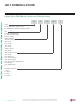
UNIT NOMENCLATURE Single Zone Wall Mount Indoor and Outdoor Units Single Zone Mega and Mega 115V Wall Mounted Engineering Manual LS N 090 HEV Family LA= Art Cool Premier / Gallery / Mirror LS= High Efficiency Wall Mount / Standard / Mega Type N = Indoor Wall Mount Unit U = Outdoor Heat Pump Unit No N or U: System Nominal Capacity (Nominal cooling capacity in Btu/h) 090 = 9,000 120 = 12,000 180 = 18,000 240 = 24,000 300/307 = 30,000 360 = 36,000 Indoor/Outdoor Product HEV = Mega HXV = Mega 115V HYV =
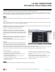
LG AIR CONDITIONER TECHNICAL SOLUTION (LATS) LG Air Conditioner Technical Solution (LATS) Software A properly designed and installed refrigerant piping system is critical to the optimal performance of LG air-conditioning systems. To assist engineers, LG offers, free of charge, LG Air Conditioner Technical Solution (LATS) software—a total design solution for LG air conditioning systems. Contact your LG Rep for the best software program for your application.
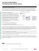
LG AIR CONDITIONER TECHNICAL SOLUTION (LATS) LATS Generates a Complete Project Report Single Zone Mega and Mega 115V Wall Mounted Engineering Manual LATS software also generates a report containing project design parameters, cooling and heating design data, system component performance, and capacity data.
PRODUCT DATA Mechanical Specifications on page 8 General Data on page 9 Electrical Data on page 12 Functions, Controls, Options on page 13 Outdoor Unit Dimensions on page 14 Indoor Unit Dimensions on page 17 Acoustic Data on page 19 Refrigerant Flow Diagrams on page 25 Indoor Unit Wiring Diagrams on page 27 Outdoor Unit Wiring Diagrams on page 29 Electrical Connections on page 32 Air Flow, Static Pressure, and Temperature Distribution on page 36 Accessories on page 48
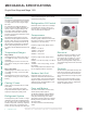
MECHANICAL SPECIFICATIONS Single Zone Mega and Mega 115V Single Zone Mega and Mega 115V Wall Mounted Engineering Manual General LG Single Zone Mega Wall Mounted systems comprise of a single outdoor unit connected to a single indoor unit with a single refrigerant circuit. An LG Single Zone Mega Wall Mounted system is a Duct-Free Split system that can operate in either cooling or heating mode.
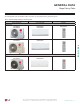
GENERAL DATA Mega Pairing Table The following table shows the available outdoor and indoor unit, along with the factory provided controller. Table 1: Single Zone Mega and Mega 115V Pairing Table Outdoor Unit Model Indoor Unit Model Controller LSU090HEV2 LSU120HEV2 LSN090HEV2 LSN120HEV2 AKB74955602 LSU180HEV2 LSU240HEV2 LSN180HEV2 LSN240HEV2 AKB74955602 LSU090HXV2 LSU120HXV2 LSN090HXV2 LSN120HXV2 AKB74955602 Mega Inverter Product Data Mega 115V 'XH WR RXU SROLF\ RI FRQWLQXRXV SURGXFW LQQRYDWL
GENERAL DATA Mega Speci cations Table 2: 6LQJOH =RQH 0HJD 6\VWHP 6SHFL¿FDWLRQV Single Zone Mega and Mega 115V Wall Mounted Engineering Manual System Model Number (IDU/ODU) LS090HEV2 (LSN090HEV2/ LSU090HEV2) LS120HEV2 (LSN120HEV2/ LSU120HEV2) LS180HEV2 (LSN180HEV2/ LSU180HEV2) LS240HEV2 (LSN240HEV2/ LSU240HEV2) 3,070 ~ 9,000 ~10,330 3,070 ~ 12,000 ~ 13,780 3,685 ~ 18,000 ~ 18,493 3,685 ~ 22,000 ~ 24,000 Cooling Capacity (Min/Rated/Max) (Btu/h) 0.72 1.142 1.5 2.
GENERAL DATA Mega 115V Speci cations Table 3: 6LQJOH =RQH 0HJD 9 6\VWHP 6SHFL¿FDWLRQV LS090HXV2 (LSN090HXV2/LSU090HXV2) LS120HXV2 (LSN120HXV2/LSU120HXV2) 3,070 ~ 9,000 ~ 10,330 0.732 3,070 ~ 10,900 ~ 12,520 0.875 3.65 12.30 20 10 3,070 ~ 12,000 ~ 13,780 1.142 3,070 ~ 12,000 ~ 13,780 1.000 3.52 10.51 19 9.
ELECTRICAL DATA Mega and Mega 115V Outdoor Units Electrical Data Single Zone Mega and Mega 115V Wall Mounted Engineering Manual Table 4: 208-230V, 60Hz, 1-Phase Single-Zone Mega System Electrical Data Table. Nominal Unit Model Hertz Voltage Voltage Range MCA Tons No. (Min. to Max.) 3/4 LS090HEV2 1 LS120HEV2 1-1/2 LS180HEV2 2 LS240HEV2 60 208 - 230 187-253 MOP Compressor Quantity Compressor Motor Outdoor Fan Motor Indoor Fan Motor RLA Cooling Heating W FLA W FLA 10.0 15 1 7.0 7.0 43 0.
FUNCTIONS, CONTROLS, OPTIONS Controllers Other Special Function Kit 1 Prefilter (Washable Anti-Bacterial / Anti-Fungal1) Hot Start Self Diagnostics Defrost Dry (Dehumidification) Auto Changeover Auto Cleaning (Coil Dry) Auto Restart Forced Operation Sleep Mode Timer 24 hour (On / Off) / 7 hour (Off) Timer (Weekly) Two Thermistor Control Low Ambient Overheat Protection Smart Diagnosis Indoor Unit Display Type Indoor Unit Display Light Energy Saving Electric Heater Wireless Remote Controller Remote Controll
Ø16-1/4 (413) 28-7/32 (717) 18-7/32 (463) Drain Hole 2-Ø13/16 (20) Air Outlet 10-1/2 (267) 3-1/2 (89) 3/16 (5) Unit: Inch (mm) Control Box 2-9/16 (65) 9-27/32 (250) 10-5/8 (270) 19-1/2 (495) PRODUCT DATA 9/16 (14) | 5 (127) 1-1/4 (31) 9-1/16 (230) 2-13/16 (71) 21° Liquid Pipe Connection (Flare) Vapor Pipe Connection (Flare) 5/8 (16) 2-7/32 (56) Service Valve Cover Power and Communication Cable Access Hole 5-3/32 (129) 14 9-1/4 (235) Single Zone Mega and Mega 115V Wall Mounted Engin
'XH WR RXU SROLF\ RI FRQWLQXRXV SURGXFW LQQRYDWLRQ VRPH VSHFL¿FDWLRQV PD\ FKDQJH ZLWKRXW QRWL¿FDWLRQ © /* (OHFWURQLFV 8 6 $ ,QF (QJOHZRRG &OLIIV 1- $OO ULJKWV UHVHUYHG ³/* ´ LV D UHJLVWHUHG WUDGHPDUN RI /* &RUS 12-11/16 (322) Air Outlet 34-1/4 (870) 23-1/16 (586) 20-9/32 (515) 15-3/16 (386) 1-1/4 (32) Vapor Pipe Connection (Flare) Liquid Pipe Connection (Flare) Service Valve Cover Control Box 3-1/16 (78) 7/8 (22) 1-1/32 (26) 12-5/16 (313) 14-13/32 (366) 25-19/32 (650) 5-5/8 (143)
OUTDOOR UNIT CORNER WEIGHT AND CENTER OF GRAVITY DIMENSIONS Figure 3: Mega and Mega 115V Outdoor Unit Corner Weight and Center of Gravity Dimensions. d Single Zone Mega and Mega 115V Wall Mounted Engineering Manual A D e c C B b a Table 7: Mega and Mega 115V Outdoor Unit Corner Weight and Center of Gravity Dimensions. Model No. Weight (lb.) Shipping Center of Gravity (Inch) Net a b c Leg (Inch) d e Corner Weight (lb.) A B C D Mega LSU090HEV2, LSU120HEV2 60.0 55.
'XH WR RXU SROLF\ RI FRQWLQXRXV SURGXFW LQQRYDWLRQ VRPH VSHFL¿FDWLRQV PD\ FKDQJH ZLWKRXW QRWL¿FDWLRQ © /* (OHFWURQLFV 8 6 $ ,QF (QJOHZRRG &OLIIV 1- $OO ULJKWV UHVHUYHG ³/* ´ LV D UHJLVWHUHG WUDGHPDUN RI /* &RUS 2-7/32 (56) 5-31/32 (152) 1/8(3) x 1/4(6) 1/4(6) x 1/8(3) 2-7/16 (61.5) 1-1/4 (31) 1-3/32 (50.2) 1-1/16 (26.2) 2 (51) 2 1-9/32(32.7) Knock-Out Refrigerant, Drain Pipe and Cable Routing Hole 2-13/32(61) 1-7/16(33.
1/8(3) x 1/4(6) 1/4(6) x 1/8(3) 2-7/16 (61.5) 1-1/4 (31) 1-3/32 (50.2) 1-1/16 (26.2) 2-3/8 (60) 2-13/32(61) 2-3/8 (60) Knock-Out Refrigerant, Drain Pipe and Cable Routing Hole Unit : Inch (mm) 5-31/32 (152) [6-11/16 (170)] Air Intake Hole 1-7/16(33.5) [2 Air -29/ 3 O utle 2 (7 t H 4)] ole 1-9/32(32.7) 5/8(15.3) Decoration Cover 34-11/32 (872) Air Outlet Hole 39-9/32 (998) [36-5/32 (918)] Air Intake Hole 'XH WR RXU SROLF\ RI FRQWLQXRXV SURGXFW LQQRYDWLRQ VRPH VSHFL¿FDWLRQV PD\ FKDQJH ZLWK
ACOUSTIC DATA Mega and Mega 115V Indoor Units Indoor Unit Sound Pressure Measurement / Sound Pressure Levels • Measurements are taken 3.3 ft away from the front of the unit. • Sound pressure levels are measured in dB(A) with a tolerance of ±1. • Data is valid at nominal operation conditions. Operating conditions are assumed to be standard.
ACOUSTIC DATA Mega and Mega 115V Indoor Units LSN120HEV2, LSN180HEV2, and LSN240HEV2 Sound Pressure Levels Figure 6: Sound Pressure Levels for Mega LSN120HEV2 Indoor Units.
ACOUSTIC DATA Mega and Mega 115V Indoor Units LSN090HXV2 and LSN120HXV2 Sound Pressure Levels Figure 9: Sound Pressure Levels for Mega 115V LSN090HXV2 Indoor Units.
ACOUSTIC DATA Mega and Mega 115V Outdoor Units Outdoor Unit Sound Pressure Measurement / Sound Pressure Levels • Measurements are taken 3.3 ft away from the front of the unit. • Sound pressure levels are measured in dB(A) with a tolerance of ±1. • Data is valid at nominal operation conditions. Operating conditions are assumed to be standard.
ACOUSTIC DATA Mega and Mega 115V Outdoor Units LSU120HEV2, LSU180HEV2, and LSU240HEV2 Sound Pressure Levels Figure 13: Sound Pressure Levels for Mega LSU120HEV2 Outdoor Units.
ACOUSTIC DATA Mega and Mega 115V Outdoor Units LSU090HXV2 and LSU120HXV2 Sound Pressure Levels Figure 16: Sound Pressure Levels for Mega 115V LSU090HXV2 Outdoor Units.
REFRIGERANT FLOW DIAGRAMS Mega LSN / LSU090, 120, 180, 240HEV2 Refrigerant Flow Diagram for Mega LSN / LSU090, 120, 180, 240HEV2 Indoor Unit Outdoor Unit Field Pipin g (Copper Tubing) Liquid Side Flare Joint 2-Way Valve Strainer M TH1 Strainer EEV (Electronic Expansion Valve) TH4 Propeller Fan M Heat Exchanger (Evaporator) Heat Exchanger (Condenser) TH2 3-Way Valve Cross Flow Fan TH3 Reversing Valve (4-Way Valve) Field Pipin g (Copper Tubing) Product Data Flare Joint TH5 Vapor Side TH6
REFRIGERANT FLOW DIAGRAMS Mega 115V LSN / LSU090, 120HXV2 Refrigerant Flow Diagram for Mega 115V LSN / LSU090, 120HXV2 Single Zone Mega and Mega 115V Wall Mounted Engineering Manual Indoor Unit Outdoor Unit Field Pipin g (Copper Tubing) Flare Joint Liquid Side 2-Way Valve Strainer M TH1 Strainer EEV (Electronic Expansion Valve) TH4 Propeller Fan M Heat Exchanger (Evaporator) Heat Exchanger (Condenser) TH2 3-Way Valve Cross Flow Fan TH3 Reversing Valve (4-Way Valve) Field Pipin g (Copper T
INDOOR UNIT WIRING DIAGRAM Mega LSN090, 120, 180, 240HEV2 Wiring Diagram for Mega LSN090, 120, 180, 240HEV2 Factory Wiring Field Wiring Option Product Data MEZ64135636 'XH WR RXU SROLF\ RI FRQWLQXRXV SURGXFW LQQRYDWLRQ VRPH VSHFL¿FDWLRQV PD\ FKDQJH ZLWKRXW QRWL¿FDWLRQ © /* (OHFWURQLFV 8 6 $ ,QF (QJOHZRRG &OLIIV 1- $OO ULJKWV UHVHUYHG ³/* ´ LV D UHJLVWHUHG WUDGHPDUN RI /* &RUS PRODUCT DATA | 27
INDOOR UNIT WIRING DIAGRAM Mega 115V LSN090HXV2 and LSN120HXV2 Wiring Diagram for Mega 115V LSN090HXV2 and LSN120HXV2 Factory Wiring Single Zone Mega and Mega 115V Wall Mounted Engineering Manual Field Wiring Option WIRED REMOTE CONTROLLER DRY CONTACT MEZ64135636 7/19 28 | PRODUCT DATA 'XH WR RXU SROLF\ RI FRQWLQXRXV SURGXFW LQQRYDWLRQ VRPH VSHFL¿FDWLRQV PD\ FKDQJH ZLWKRXW QRWL¿FDWLRQ © /* (OHFWURQLFV 8 6 $ ,QF (QJOHZRRG &OLIIV 1- $OO ULJKWV UHVHUYHG ³/* ´ LV D UHJLVWHUHG WUDGHPDUN RI /*
OUTDOOR UNIT WIRING DIAGRAM Mega LSU090HEV2 and LSU120HEV2 Wiring Diagram for Mega LSU090HEV2 and LSU120HEV2 Factory Wiring Field Wiring Option Product Data MEZ64835136 'XH WR RXU SROLF\ RI FRQWLQXRXV SURGXFW LQQRYDWLRQ VRPH VSHFL¿FDWLRQV PD\ FKDQJH ZLWKRXW QRWL¿FDWLRQ © /* (OHFWURQLFV 8 6 $ ,QF (QJOHZRRG &OLIIV 1- $OO ULJKWV UHVHUYHG ³/* ´ LV D UHJLVWHUHG WUDGHPDUN RI /* &RUS PRODUCT DATA | 29
OUTDOOR UNIT WIRING DIAGRAM Mega LSU180HEV2 and LSU240HEV2 Wiring Diagram for Mega LSU180HEV2 and LSU240HEV2 Factory Wiring Single Zone Mega and Mega 115V Wall Mounted Engineering Manual Field Wiring Option MEZ66177431 30 | PRODUCT DATA 'XH WR RXU SROLF\ RI FRQWLQXRXV SURGXFW LQQRYDWLRQ VRPH VSHFL¿FDWLRQV PD\ FKDQJH ZLWKRXW QRWL¿FDWLRQ © /* (OHFWURQLFV 8 6 $ ,QF (QJOHZRRG &OLIIV 1- $OO ULJKWV UHVHUYHG ³/* ´ LV D UHJLVWHUHG WUDGHPDUN RI /* &RUS
OUTDOOR UNIT WIRING DIAGRAM Mega 115V LSU090HXV2 and LSU120HXV2 Wiring Diagram for Mega 115V LSU090HXV2 and LSU120HXV2 Factory Wiring Field Wiring Option REVERSING VALVE REACTOR OUTDOOR PIPE TH. D-PIPE TH. MVC JIG BK CN_COIL1 CN_COIL2 CN_TH1 CN_TH2 CN_EEV1 250 V / T3.15 A RY_4WAY_AC CN_4WAY_AC CN_FAN_DC TERMINAL BLOCK CN_LGMV GN/YL BK 250 V / T20 A RD CN_COMP 250 V / T3.
ELECTRICAL CONNECTIONS Single Zone Mega and Mega 115V Wall Mounted Engineering Manual General Power Wiring / Communications Cable Guidelines • • • • • • Follow manufacturer’s circuit diagrams displayed on the inside of the control box cover. Confirm power source specifications. Properly ground the outdoor unit and the indoor unit per National Electrical Code (NEC) and local codes. Connect the wiring firmly so that the wires cannot be easily pulled out. Confirm that the electrical capacity is sufficient.
ELECTRICAL CONNECTIONS Figure 18: LS090HEV2 and LS120HEV2 General Power / Communications System Schematic. Figure 19: LS180HEV2 and LS240HEV2 General Power / Communications System Schematic. Power Supply Power Supply Circuit Breaker Circuit Breaker Indoor Unit Ground Wiring Indoor Unit Ground Wiring Outdoor Unit Outdoor Unit Power Supply Product Data Figure 20: LS090HXV2 and LS120HXV2 General Power / Communications System Schematic. Figure 21: Terminal Block Wiring Diagram LS090-120HEV2.
ELECTRICAL CONNECTIONS Figure 22: Terminal Block Wiring Diagram LS180HEV2, LS240HEV2. Single Zone Mega and Mega 115V Wall Mounted Engineering Manual LS180HEV2, LS240HEV2 Figure 23: Terminal Block Wiring Diagram LS090HXV2, LS120HXV2 LS090, 120HXV2 115 VAC • Use a conduit for the communications cable / power wiring from the outdoor unit to the indoor units.
ELECTRICAL CONNECTIONS Figure 26: PZCWRC1 LG Wired Remote Extension Cable for Use with the Mega 115V. Verify the connectors are properly inserted. C/BOX Cable (Plug type) FAN SPEED TEMP OPER MODE Extension cable Figure 27: Wired Controller Connection on the Mega 115V Indoor Unit Terminal Block. Indoor Unit Terminal Block 2 3 CN-REMO CN-CC RD BL BR 1(L1) :KHQ XVLQJ ¿HOG VXSSOLHG FRQWUROOHU FDEOH PDNH VXUH WR FRQQHFW WKH \HOORZ WR \HOORZ (communications wire), red to red (12V power wire), and bl
AIR FLOW, STATIC PRESSURE, AND TEMPERATURE DISTRIBUTION Table 14: Mega and Mega 115V Outdoor Unit Air Flow Rate and Static Pressure. Single Zone Mega and Mega 115V Wall Mounted Engineering Manual Mega Model No. Air Flow Rate (CFM) Static Pressure (in. WG) LSU090HEV2, LSU120HEV2 LSU180HEV2, LSU240HEV2 953 1,730 0.0284 0.0387 953 0.0284 Mega 115V LSU090HXV2, LSU120HXV2 LSN090HEV2 Cooling Temperature [ C ( F)] Air Velocity [m/s (ft./s)] 2(6.6) 0.3(1) 0.5(1.6) 1(3.3) m 2 ft. 6.6 1 3.
AIR FLOW AND TEMPERATURE DISTRIBUTION LSN090HEV2, continued. Heating Air Velocity [m/s (ft./s)] Temperature [ 2(6.6) 0.3(1) 0.5(1.6) 1(3.3) m 2 ft. 6.6 1 3.3 0 0 ( )] m ft. 6.6 28(82) 2 26(79) 22(72) 24(75) m 10 8 6 4 2 0 m 10 8 6 4 2 0 ft. 32.8 26.2 19.7 13.1 6.6 0 ft. 32.8 26.2 19.7 13.1 6.6 0 1 3.3 0 0 Side View Discharge Angle : 55 (From the floor Vertical Louver : Center Fan Speed : Power ) Air Velocity [m/s (ft./s)] m ft. 5 16.4 0.3(1) m ft. 5 16.
AIR FLOW AND TEMPERATURE DISTRIBUTION LSN120HEV2 Single Zone Mega and Mega 115V Wall Mounted Engineering Manual Cooling Temperature [ C ( F)] Air Velocity [m/s (ft./s)] 0.5(1.6) ft. 6.6 1 3.3 m 24(75) 2(6.6) 0.3(1) m 2 1(3.3) 0 0 22(72) 2 ft. 6.6 1 3.3 0 0 26(79) 28(82) m 10 8 6 4 2 0 m 10 8 6 4 2 0 ft. 32.8 26.2 19.7 13.1 6.6 0 ft. 32.8 26.2 19.7 13.1 6.
AIR FLOW AND TEMPERATURE DISTRIBUTION LSN120HEV2, continued. Heating Air Velocity [m/s (ft./s)] Temperature [ C ( F)] m 2 ft. 6.6 1 3.3 0 0 22(72) m 2 ft. 6.6 1 3.3 0 0 28(82) 2(6.6) 0.3(1) 0.5(1.6) 1(3.3) m 10 8 6 4 2 ft. 32.8 26.2 19.7 13.1 6.6 0 m 10 8 0 ft. 32.8 26.2 24(75) 26(79) 6 4 2 0 19.7 13.1 6.6 0 Side View Discharge Angle : 55 (From the floor Vertical Louver : Center Fan Speed : Power ) Air Velocity [m/s (ft./s)] m ft. 5 16.4 0.3(1) m ft.
AIR FLOW AND TEMPERATURE DISTRIBUTION LSN180HEV2 Single Zone Mega and Mega 115V Wall Mounted Engineering Manual Cooling Air Velocity [m/s (ft./s)] Temperature [ഒ (ഘ)] 2(6.6) 0.3(1) 0.5(1.6) m 2 ft. 6.6 1 3.3 0 0 24(75) 28(82) 22(72) 20(68) 26(79) 1(3.3) m 10 8 6 4 2 0 m 10 8 6 4 2 0 ft. 32.8 26.2 19.7 13.1 6.6 0 ft. 32.8 26.2 19.7 13.1 6.6 0 m 2 ft. 6.6 1 3.
AIR FLOW AND TEMPERATURE DISTRIBUTION LSN180HEV2, continued. Heating Air Velocity [m/s (ft./s)] 0.3(1) 0.5(1.6) Temperature [ഒ (ഘ)] 2(6.6) 1(3.3) 1.5(4.9) m 2 ft. 6.6 1 3.3 0 0 m 24(75) 32(90) 2 ft. 6.6 1 3.3 0 0 28(82) 26(79) m 10 8 6 4 2 0 m 10 8 6 4 2 0 ft. 32.8 26.2 19.7 13.1 6.6 0 ft. 32.8 26.2 19.7 13.1 6.6 0 Side View Discharge Angle : 45 (From the floor Vertical Louver : Center Fan Speed : Power ) Air Velocity [m/s (ft./s)] m ft. 5 16.4 m ft.
AIR FLOW AND TEMPERATURE DISTRIBUTION LSN240HEV2 Cooling Temperature [ C ( F)] Single Zone Mega and Mega 115V Wall Mounted Engineering Manual Air Velocity [m/s (ft./s)] 2(6.6) 0.3(1) 0.5(1.6) 1.5(4.9) m 2 ft. 6.6 1 3.3 m 28(82) 22(72) 18(64) 2 ft. 6.6 1 3.3 0 0 24(75) 26(79) 1(3.3) 0 0 m 10 8 6 4 2 0 m 10 8 6 4 2 0 ft. 32.8 26.2 19.7 13.1 6.6 0 ft. 32.8 26.2 19.7 13.1 6.
AIR FLOW AND TEMPERATURE DISTRIBUTION LSN240HEV2, continued. Heating Air Velocity [m/s (ft./s)] 0.3(1) 0.5(1.6) Temperature [ഒ (ഘ)] 1(3.3) 1.5(4.9) 2(6.6) m 2 ft. 6.6 1 3.3 0 0 m 24(75) ft. 6.6 32(90) 2 30(86) 28(82) 26(79) m 10 8 6 4 2 0 m 10 8 6 4 2 0 ft. 32.8 26.2 19.7 13.1 6.6 0 ft. 32.8 26.2 19.7 13.1 6.6 0 1 3.3 0 0 Side View Discharge Angle : 45 (From the floor Vertical Louver : Center Fan Speed : Power ) Air Velocity [m/s (ft./s)] m ft. 5 16.
AIR FLOW AND TEMPERATURE DISTRIBUTION LSN090HXV2 Cooling Single Zone Mega and Mega 115V Wall Mounted Engineering Manual Air Velocity [m/s (ft./s)] Temperature [ഒ (ഘ)] 2(6.6) 0.3(1) ft. 6.6 1 3.3 m 0 0 ft. 6.6 22(72) 2 24(75) 26(79) 28(82) 1(3.3) 0.5(1.6) m 2 m 10 8 6 4 2 0 m 10 8 6 4 2 0 ft. 32.8 26.2 19.7 13.1 6.6 0 ft. 32.8 26.2 19.7 13.1 6.6 0 1 3.
AIR FLOW AND TEMPERATURE DISTRIBUTION LSN090HXV2, continued. Heating Air Velocity [m/s (ft./s)] Temperature [ഒ (ഘ)] 2(6.6) 0.3(1) 0.5(1.6) 1(3.3) m 2 ft. 6.6 1 3.3 0 0 28(82) 26(79) 24(75) m 10 8 6 4 2 0 m 10 8 6 4 2 0 ft. 32.8 26.2 19.7 13.1 6.6 0 ft. 32.8 26.2 19.7 13.1 6.6 0 m 2 ft. 6.6 1 3.3 0 0 Side View Discharge Angle : 55 (From the floor Vertical Louver : Center Fan Speed : Power ) Air Velocity [m/s (ft./s)] m ft. 5 16.4 4 13.1 m ft. 5 16.4 0.5(1.
AIR FLOW AND TEMPERATURE DISTRIBUTION LSN120HXV2 Cooling Single Zone Mega and Mega 115V Wall Mounted Engineering Manual Air Velocity [m/s (ft./s)] Temperature [ഒ (ഘ)] 2(6.6) 0.3(1) ft. 6.6 1 3.3 22(72) 24(75) 26(79) 28(82) 1(3.3) 0.5(1.6) m 2 0 0 m 10 8 6 4 2 0 m 10 8 6 4 2 0 ft. 32.8 26.2 19.7 13.1 6.6 0 ft. 32.8 26.2 19.7 13.1 6.6 0 m 2 ft. 6.6 1 3.
AIR FLOW AND TEMPERATURE DISTRIBUTION LSN120HXV2, continued. Heating Air Velocity [m/s (ft./s)] Temperature [ഒ (ഘ)] 2(6.6) 0.3(1) 0.5(1.6) 1(3.3) m 2 ft. 6.6 1 3.3 0 0 28(82) 26(79) 24(75) m 10 8 6 4 2 0 m 10 8 6 4 2 0 ft. 32.8 26.2 19.7 13.1 6.6 0 ft. 32.8 26.2 19.7 13.1 6.6 0 m 2 ft. 6.6 1 3.3 0 0 Side View Discharge Angle : 55 (From the floor Vertical Louver : Center Fan Speed : Power ) Air Velocity [m/s (ft./s)] m ft. 5 16.4 4 13.1 m ft. 5 16.4 0.5(1.
ACCESSORIES Single Zone Mega and Mega 115V Wall Mounted Engineering Manual LG Monitoring View (LGMV) Diagnostic Software and Cable LGMV software allows the service technician or commissioning agent to connect a computer USB port to the outdoor unit main printed circuit board (PCB) using an accessory cable without the need for a separate interface device.
ACCESSORIES LG Smart Inverter Monitoring System (SIMS) SIMS can be used to display and graph operational data for single zone systems and respective components (indoor unit and outdoor unit). SIMS also displays error codes and a troubleshooting guide. SIMs consists of a hardware Wireless Local Area Network (WLAN) module, an interface cable, and a free downloadable application (app) for iOS® or Android™.
PERFORMANCE DATA Cooling Capacity Data on page 51 Heating Capacity Data on page 54 Maximum Heating Capacity Data on page 56 Equipment Selection Procedure on page 59
PERFORMANCE DATA Cooling Capacity LS090HEV2, LS120HEV2 Cooling Capacity Table for LS090HEV2 (LSU090HEV2 + LSN090HEV2) Table 15: LSN090HEV2 / LSU120HEV2 Cooling Capacities. Outdoor Air 64 / 53 Temp. TC SHC (°F DB) 5.51 5.92 6.01 6.24 6.47 6.70 6.94 7.17 7.40 7.63 7.56 7.49 7.43 7.36 7.29 7.22 7.15 6.96 6.77 6.59 6.35 6.21 6.02 4.90 5.26 5.34 5.55 5.75 5.96 6.17 6.37 6.58 6.79 6.72 6.66 6.60 6.54 6.48 6.42 6.36 6.19 6.02 5.86 5.65 5.52 5.63 0.31 0.30 0.31 0.33 0.36 0.38 0.40 0.43 0.45 0.47 0.49 0.52 0.54 0.
PERFORMANCE DATA Cooling Capacity LS180HEV2, LS240HEV2 Cooling Capacity Table for LS180HEV2 (LSU180HEV2 + LSN180HEV2) Single Zone Mega and Mega 115V Wall Mounted Engineering Manual Table 17: LSN0180HEV2 / LSU180HEV2 Cooling Capacities. Outdoor Air 64 / 53 Temp. TC SHC (°F DB) 14 23 25 30 35 40 45 50 55 60 65 70 75 80 85 90 95 100 105 110 115 118 122 11.02 11.83 12.02 12.48 12.95 13.41 13.87 14.34 14.80 15.27 15.13 14.99 14.85 14.71 14.57 14.43 14.29 13.92 13.55 13.17 12.70 12.42 12.05 8.76 9.40 9.55 9.
PERFORMANCE DATA Cooling Capacity LS090HXV2, LS120HXV2 Cooling Capacity Table for LS090HXV2 (LSU090HXV2 + LSN090HXV2) Table 19: LSN090HXV2 / LSU090HXV2 Cooling Capacities. Outdoor Air Temp. (°F DB) 5.51 5.92 6.01 6.24 6.47 6.70 6.94 7.17 7.40 7.63 7.56 7.49 7.43 7.36 7.29 7.22 7.15 6.96 6.77 6.59 6.35 6.21 6.02 4.90 5.26 5.34 5.55 5.75 5.96 6.17 6.37 6.58 6.79 6.72 6.66 6.60 6.54 6.48 6.42 6.36 6.19 6.02 5.85 5.65 5.52 5.63 PI TC 68 / 57 SHC 0.31 0.31 0.32 0.34 0.36 0.39 0.41 0.43 0.46 0.48 0.50 0.
PERFORMANCE DATA Heating Capacity LS090HEV2, LS120HEV2, LS180HEV2 Heating Capacity Table for LS090HEV2 (LSU090HEV2 + LSN090HEV2) Table 21: LSN090HEV2 / LSU090HEV2 Heating Capacities. Single Zone Mega and Mega 115V Wall Mounted Engineering Manual Outdoor Air Temp. °F DB °F WB 16 17 19 24 32 41 43 47 53 59 64 70 75 14 15 17 23 30 38 40 43 50 53 57 61 65 Indoor Air Temperature (°F DB) TC 60 6.90 6.94 7.04 7.72 9.25 10.62 10.96 11.47 11.58 11.85 12.10 12.33 12.50 PI TC 0.70 0.71 0.72 0.75 0.81 0.86 0.
PERFORMANCE DATA Heating Capacity LS240HEV2, LS090HXV2, LS120HXV2 Heating Capacity Table for LS240HEV2 (LSU240HEV2 + LSN240HEV2) Table 24: LSN240HEV2 / LSU240HEV2 Heating Capacities. Outdoor Air Temp. °F DB °F WB 16 17 19 24 32 41 43 47 53 59 64 70 75 14 15 17 23 30 38 40 43 50 53 57 61 65 Indoor Air Temperature (°F DB) TC 60 13.92 14.02 14.21 15.58 18.68 21.43 22.12 23.15 23.38 23.91 24.42 24.89 25.23 PI TC 1.54 1.56 1.59 1.65 1.78 1.90 1.92 1.97 1.99 2.01 2.05 2.08 2.11 13.50 13.59 13.77 15.11 18.
PERFORMANCE DATA Maximum Heating Capacity LS090HEV2, LS120HEV2 Maximum Heating Capacity Table for LS090HEV2 (LSU090HEV2 + LSN090HEV2) Single Zone Mega and Mega 115V Wall Mounted Engineering Manual Table 27: LSN090HEV2 / LSU090HEV2 Heating Capacities. Outdoor Air Temp. °F DB °F WB 16 17 19 24 32 41 43 47 53 59 64 70 75 14 15 17 23 30 38 40 43 50 53 57 61 65 Indoor Air Temperature (°F DB) TC 60 8.37 8.68 9.17 10.07 10.97 11.84 12.20 12.93 12.74 12.59 12.81 12.86 13.05 PI TC 1.15 1.16 1.16 1.17 1.13 1.
PERFORMANCE DATA Maximum Heating Capacity LS180HEV2, LS240HEV2 Maximum Heating Capacity Table for LS180HEV2 (LSU180HEV2 + LSN180HEV2) Table 29: LSN180HEV2 / LSU180HEV2 Heating Capacities. Outdoor Air Temp. °F DB °F WB 16 17 19 24 32 41 43 47 53 59 64 70 75 14 15 17 23 30 38 40 43 50 53 57 61 65 Indoor Air Temperature (°F DB) TC 60 14.59 15.14 15.99 17.55 19.13 20.64 21.26 22.54 22.21 21.95 22.34 22.42 22.74 PI TC 2.08 2.10 2.11 2.12 2.05 1.91 1.82 1.75 1.70 1.67 1.62 1.55 1.39 14.38 14.93 15.77 17.
PERFORMANCE DATA Maximum Heating Capacity LS090HXV2, LS120HXV2 Maximum Heating Capacity Table for LS090HXV2 (LSU090HXV2 + LSN090HXV2) Single Zone Mega and Mega 115V Wall Mounted Engineering Manual Table 31: LSN090HXV2 / LSU090HXV2 Heating Capacities. Outdoor Air Temp. °F DB °F WB 16 17 19 24 32 41 43 47 53 59 64 70 75 14 15 17 23 30 38 40 43 50 53 57 61 65 Indoor Air Temperature (°F DB) TC 60 8.37 8.68 9.17 10.07 10.97 11.84 12.20 12.93 12.74 12.59 12.81 12.86 13.05 PI TC 1.15 1.16 1.16 1.17 1.13 1.
EQUIPMENT SELECTION PROCEDURE Correction Factors Cooling / Heating Correction Factors For Single Zone Mega Wall Mounted systems, calculate the equivalent length of the liquid line from the outdoor unit to the indoor unit. Also, determine the elevation difference of the indoor unit above or below the outdoor unit. Find corresponding cooling or heating capacity correction factors as shown below.
EQUIPMENT SELECTION PROCEDURE Correction Factors Single Zone Mega and Mega 115V Wall Mounted Engineering Manual Defrost Correction Factor for Heating Operation The outdoor unit heating capacity may need to be adjusted for frost accumulation on air-cooled systems. If design day conditions are below the dewpoint of the surrounding air, frost may not be a problem and no correction factor is needed.
APPLICATION GUIDELINES Placement Considerations on page 62 Installing Outdoor Units Indoors on page 67 Refrigerant Piping Design on page 70
PLACEMENT CONSIDERATIONS Indoor Unit Selecting the Best Location for the Indoor Unit Single Zone Mega and Mega 115V Wall Mounted Engineering Manual Follow recommended best practices when choosing an indoor location for the single zone indoor unit. Figure 30: Mega Indoor Unit Clearance Requirements. Unit: Inch (mm) Dos • Follow the table at right for minimum clearance of indoor unit from the top of the unit to the ceiling.
PLACEMENT CONSIDERATIONS Outdoor Unit Selecting the Best Location for the Outdoor Unit DANGER • Do not install the unit in an area where combustible gas will generate, flow, stagnate, or leak. These conditions can cause a fire, resulting in bodily injury or death. • Do not install the unit in a location where acidic solution and spray (sulfur) are often used as it can cause bodily injury or death.
PLACEMENT CONSIDERATIONS Outdoor Unit Single Zone Mega and Mega 115V Wall Mounted Engineering Manual Planning for Snow and Ice, continued. When deciding on a location to place the outdoor unit, be sure to choose an area where run-off from defrost will not accumulate and freeze on sidewalks or driveways, which will create unsafe conditions. Properly install and insulate any drain hoses to prevent the hose from freezing, cracking, leaking, and causing unsafe conditions from frozen condensate.
PLACEMENT CONSIDERATIONS Outdoor Unit Oceanside Applications Figure 34: Oceanside Placement Using Windbreak. Use of a Windbreak to Shield from Sea Wind Windbreak Ocean winds will cause corrosion, particularly on the condenser and HYDSRUDWRU ¿QV ZKLFK LQ WXUQ FRXOG FDXVH SURGXFW PDOIXQFWLRQ RU LQHI¿FLHQW SHUIRUPDQFH • • • • • Sea wind Additional anti-corrosion treatment will need to be applied to the outdoor unit at oceanside locations. Figure 35: Placement Using Building as Shield.
PLACEMENT CONSIDERATIONS Outdoor Unit Single Zone Mega and Mega 115V Wall Mounted Engineering Manual Minimum Allowable Clearance and Service Access Requirements Proper clearance for the outdoor unit coil is critical for proper operation. When installing the outdoor unit, consider service, inlet and outlet, and minimum allowable space requirements as illustrated in the diagrams below. • Include enough space for airflow and for service access.
PLACEMENT CONSIDERATIONS Installing Outdoor Units Indoors Installing Outdoor Units Indoors Single Zone Mega and Mega 115V Wall Mount outdoor units are engineered to be mounted outdoors and include technology designed to minimize the negative effects of winter weather’s freezing rain, sleet, and snow. Some building projects, however, necessitate placing the HVAC outdoor units indoors: • Lack of ground space. • Lack of an appropriate outdoor location that meets system design requirements.
PLACEMENT CONSIDERATIONS Single Zone Mega and Mega 115V Wall Mounted Engineering Manual Installing Outdoor Units Indoors Provide a means to drain the condensate generated during heating mode and defrost cycle in addition to rainwater that infiltrates the inlet louver enclosed area. • Install a field-provided drain pan under the outdoor units and provide a path to a nearby floor drain.
PLACEMENT CONSIDERATIONS Installing Outdoor Units Indoors Open Rate by Louver Radian Figure 39: Open Rate by Louver Radian Formula. W h ho H Application Guidelines ho = h * COS Total Area (A) = H * W Number of Open Spaces (N) = (Number of Louvers - 1) Effective Area (Af) = ho * W * N Louver Open Rate (n) = Af / A Af = A * n Side View Effective Cross Section Area Front View Confirming Air Flow Rate / Total Opening Rate Figure 40: Example of Installing Outdoor Unit Indoors. • Example: LSU180HSV5.
REFRIGERANT PIPING DESIGN Single Zone Mega and Mega 115V Wall Mounted Engineering Manual Design Guideline Summary Device Connection Limitations Figure 41: Mega and Mega 115V System Layout. Single-zone systems consist of one outdoor unit and one indoor unit. One of the most critical elements of a single zone system is the refrigerant piping. The table below lists pipe length limits that must be followed in the design of a Single Zone Mega or Mega 115V refrigerant pipe system.
20001747 ISO 9001: 2008 LG ELECTRONICS INC. LG Electronics, U.S.A., Inc. Air Conditioning Technologies 4300 North Point Parkway Alpharetta, Georgia 30022 www.lghvac.