
Quick Setup Guide


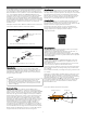

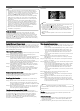
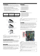

Table Of Contents

8
• Unless the applicable DIP switch is set properly, the system
may not work.
• If a specific function is desired, request that the installer set
the appropriate DIP switch during installation.
NOTE
!
LGMV monitoring software is encouraged for use in future
diagnostic and maintenance related checks.
NOTE
!
Final Installation Procedures
Test Run Procedure
3. Operate the system in cooling mode for 15 to 20 minutes.
4. Evaluate performance as the system runs, verifying the outdoor
unit, and all indoor units and branch distribution units (Multi F
MAX systems only) are working properly. Make notes as needed
to address any issues that might be found.
• Check the system refrigerant charge:
• Measure the pressure from the gas side service valve.
• Measure the indoor unit inlet and outlet air temperatures.
Verify the difference between the intake temperature and the
discharge is more than 15°F.
• See table below for the optimum condition of the gas side
pressure (again, system is in cooling mode).
Optimum Conditions of the Gas Side Pressure.
Multi F Systems
Additional charge (oz.)
= (Installed Length of Branch [A]
– Chargeless Pipe Length [L]) x a
+ (Installed Length of Branch [B]
– Chargeless Pipe Length [L]) x a
+ (Installed Length of Branch [C]
– Chargeless Pipe Length [L]) x a
+ (Installed Length of Branch [D]
– Chargeless Pipe Length [L]) x a
- CF (Correction Factor) x 5.29
Multi F MAX Systems
Additional charge (oz.)
= (Total Main Piping Length [A]
– Chargeless Pipe Length of Main Pipe [L]) x a
+ (Installed Length of Branch [B1]
– Chargeless Pipe Length [B]) x b
+ (Installed Length of Branch [B2]
– Chargeless Pipe Length [B]) x b
+ (Installed Length of Branch [B3]
– Chargeless Pipe Length [B]) x b
- CF (Correction Factor) x 3.53
Refrigerant Type
Outside Ambient
Temperature
Gas Side Service
Valve Pressure
R410A 95 °F 120~135 psig
If the pressure is >135 psig, the system is most likely
overcharged, and refrigerant must be removed. If the pressure
is <120 psig, the system is most likely undercharged and
refrigerant must be added.
NOTE
!
• Number of installed length of branches depends on system
specifications.
• CF = Maximum number of connectible indoor units – Total
number of connected indoor units
NOTE
!
Inlet and Outlet Temperature Locations on Various Indoor Units.
DIP-SW01D
12345678910
Outlet Temperature
Discharge Air
Inlet Temperature
Outlet Temperature
Discharge Air
Inlet Temperature
Outlet Temperature
Discharge Air
Inlet Temperature
The circuit breaker must be turned off or the power source of
the product must be shut off before setting the DIP switch.
There is risk of physical injury or death due to electric shock.
WARNING
!
Installing the Remote Controller Batteries
As part of the test run, two (2) AAA (1.5V) batteries need to be
inserted into the remote controller, and the remote controller may
need to be powered on to operate the indoor units (depending on
the indoor units included in the system). To insert the batteries
follow the steps below. For information on using the remote
controller, refer to its owner’s manual.
Refrigerant Charge
LG Multi F and Multi F MAX outdoor units ship from the factory
with a charge of R410A refrigerant. A trim charge may need to be
added to take into account additional piping length. To find the
R410A factory charge of each outdoor unit, see the Multi F / Multi
F MAX Outdoor Unit Installation Manuals.
To determine the additional refrigerant that is needed, apply the
formulas below, and record the results. If the total additional
refrigerant charge value is a negative number, then an additional
trim charge does not need to be added to the system.
Optional Modes
Multi F and Multi F MAX outdoor units include optional functions
such as mode locks for cooling and heating, night quiet modes,
and others. The modes are set by powering off the system, setting
the applicable DIP switches on the PCB of the outdoor unit, and
then turning the power back on. These modes must only be set by
an authorized, trained and licensed technician during the
installation process. For a complete list of optional modes that are
available for specific outdoor units, and the detailed procedures
necessary to properly set the modes, see the complete Multi F /
Multi F MAX Installation Manual.
Location of the Outdoor Unit DIP Switch Example.
(Appearances May Differ Depending on Model).